Unlock instant, AI-driven research and patent intelligence for your innovation.

Magnetoresistive random access memory

a random access memory and magnetism technology, applied in the field of magnetism random access memory, can solve the problems of increasing the possibility of occurrence of a write error (read disturbance) in a memory cell, reducing the read speed, and reducing the ability of spin-transfer-torque-write mram to replace a dram, so as to achieve the effect of suppressing a write error

Active Publication Date: 2009-07-30
KIOXIA CORP
View PDF3 Cites 17 Cited by
  • Summary
  • Abstract
  • Description
  • Claims
  • Application Information

AI Technical Summary

Benefits of technology

[0010]According to an aspect of the present invention, there is provided a magnetoresistive random access memory comprising: a memory cell array in which a plurality of memory cells which hold data are arranged in a first direction and a second direction; a plurality of word lines which are arranged to run in the first direction, and to which a word line voltage for selecting the memory cell is applied; a plurality of bit lines which are arranged to run in the second direction, and to which a read/write voltage for reading data from or writing data to the memory cell is applied; a plurality of source lines which are arranged to run in the second direction, and to which the read/write voltage for reading data from or wri...

Problems solved by technology

When the read current is large, therefore, the possibility of occurrence of a write error (read disturbance) in a memory cell increases.
However, decreasing the read current is equivalent to decreasing the resistance against variations in a circuit and decreasing the read speed.
This makes it difficult for the spin-transfer-torque-write MRAM to replace a DRAM required to have a large capacity and high speed.
However, this method has no special improvement on a read operation.
In the prior art as explained above, the read current must be decreased because read disturbance may occur if the read current increases.
This makes it impossible to provide a high-speed MRAM.

Method used


Image

  • Magnetoresistive random access memory
  • Magnetoresistive random access memory
  • Magnetoresistive random access memory

Examples


first embodiment

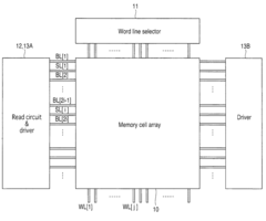
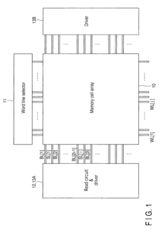
[0021]Embodiments of the present invention will be explained below with reference to the accompanying drawing. FIG. 1 shows the main parts of a spin-transfer-torque-write magnetoresistive random access memory (MRAM) according to the first embodiment of the present invention.

[0022]A memory cell array 10 is formed by arranging electrically programmable nonvolatile memory cells in a matrix. A plurality of word lines WL running in the first direction are connected to a word line selector 11. A plurality of bit lines BL running in the second direction are connected to a read circuit 12 and drivers 13A and 13B. A plurality of source lines SL are also connected to the drivers 13A and 13B. The read circuit 12 is placed at one end of each of the plurality of bit lines BL running in the second direction. The drivers 13A and 13B are arranged at the two ends of each of the plurality of bit lines BL and the plurality of source lines SL running in the second direction.

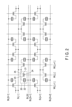
[0023]FIGS. 2 to 5 illustrat...

second embodiment

[0032]FIGS. 7 and 8 illustrate the arrangement and read method of a tunnel magnetoresistive element 22 of a spin-transfer-torque-write MRAM according to the second embodiment of the present invention. The arrangements of the main components of the second embodiment are the same as those of the first embodiment shown in FIGS. 1 to 4.

[0033]As shown in FIG. 7, the difference from the first embodiment is that a magnetization direction 58 in a fixed layer 50 of the tunnel magnetoresistive element 22 is fixed not in the direction from a drain diffusion layer 42 to a bit line BL[2i], but in the opposite direction, i.e., the direction from the bit line BL[2i] to the drain diffusion layer 42. Accordingly, the direction of SST 53 is also opposite to that in the first embodiment, i.e., the SST 53 is generated in the direction from a free layer 51 to the fixed layer 50. Therefore, a magnetic field HBL 54 is generated in the tunnel magnetoresistive element 22 in a direction to suppress the STT 5...

third embodiment

[0036]FIGS. 6 and 9 illustrate the arrangement and read method of a tunnel magnetoresistive element 22 of a spin-transfer-torque-write MRAM according to the third embodiment of the present invention. The arrangements of the major parts of the third embodiment are the same as those of the first embodiment shown in FIGS. 1 to 3.

[0037]As shown in FIG. 9, the difference from the first embodiment is that in the tunnel magnetoresistive element 22, a fixed layer 60, insulating layer 62, and free layer 61 are arranged between a drain diffusion layer 42 and bit line BL[2i] in the order named from the side of the bit line BL[2i]. This arrangement order is opposite to that of the first embodiment. In addition, a magnetization direction 68 in the fixed layer 60 is fixed in the direction from the bit line BL[2i] to the drain diffusion layer 42. During a read operation, STT 63 is generated in the same direction as that of the first embodiment, i.e., in the direction from the free layer 61 to the ...


PUM


Abstract

A word line voltage is applied to a plurality of word lines. A read / write voltage is applied to a plurality of bit lines. The read / write voltage is applied to a plurality of source lines. A word line selector selects the word line and applies the word line voltage. A driver applies a predetermined voltage to the bit line and the source line, thereby supplying a current to the memory cell. A read circuit reads a first current having flowed through the memory cell, and determines data stored in the memory cell. When performing the read, the driver supplies a second current to second bit lines among other bit lines, which are adjacent to the first bit line through which the first current has flowed. The second current generates a magnetic field in a direction to suppress a write error in the memory cell from which data is to be read.

Description

CROSS-REFERENCE TO RELATED APPLICATIONS[0001]This application is based upon and claims the benefit of priority from prior Japanese Patent Application No. 2008-016173, filed Jan. 28, 2008, the entire contents of which are incorporated herein by reference.BACKGROUND OF THE INVENTION[0002]1. Field of the Invention[0003]The present invention relates to a magnetoresistive random access memory.[0004]2. Description of the Related Art[0005]The magnetoresistive random access memory (MRAM) is a device that stores information by using the magnetoresistive effect. The MRAM has volatility, a high operating speed, a high integration degree, and high reliability, and hence is expected as a nonvolatile random access memory capable of replacing a DRAM, EEPROM, and the like. In particular, a spin-transfer-torque-write MRAM using magnetization reversal caused by spin current transfer has been attracting attention in recent years because the device has high scalability to micropatterning.[0006]In the s...

Claims


Application Information

Patent Timeline
IPC IPC(8): G11C11/02G11C11/416G11C8/08
CPCG11C11/16G11C11/1673G11C11/1675
Inventor ITAGAKI, KIYOTAROUEDA, YOSHIHIRO
Owner KIOXIA CORP
Features
  • R&D
  • Intellectual Property
  • Life Sciences
  • Materials
  • Tech Scout
  • Unparalleled Data Quality
  • Higher Quality Content
  • 60% Fewer Hallucinations
Learn More