
Image noise reduction apparatus and method, recorded medium recorded the program performing it

Inactive Publication Date: 2009-07-30
MTEKVISION CO LTD
View PDF15 Cites 18 Cited by
  • Summary
  • Abstract
  • Description
  • Claims
  • Application Information

AI Technical Summary

Benefits of technology

[0013]Accordingly, the present invention provides an image noise reduction apparatus and a method thereof, and a recoding medium recorded with a program performing the method that can prevent a noise component of a surrounding part from being amplified by using a different low pass filter in a center part and a surrounding part of an image and can acquire the resolution and quality of the desired image.
[0014]The present invention also provides an image noise reduction apparatus and a method thereof, and a recoding medium recorded with a program performing the method that can recover the features of an original image in a center part and can filter an increased noise caused by the multiplication of a gain in a surrounding part through image analysis.
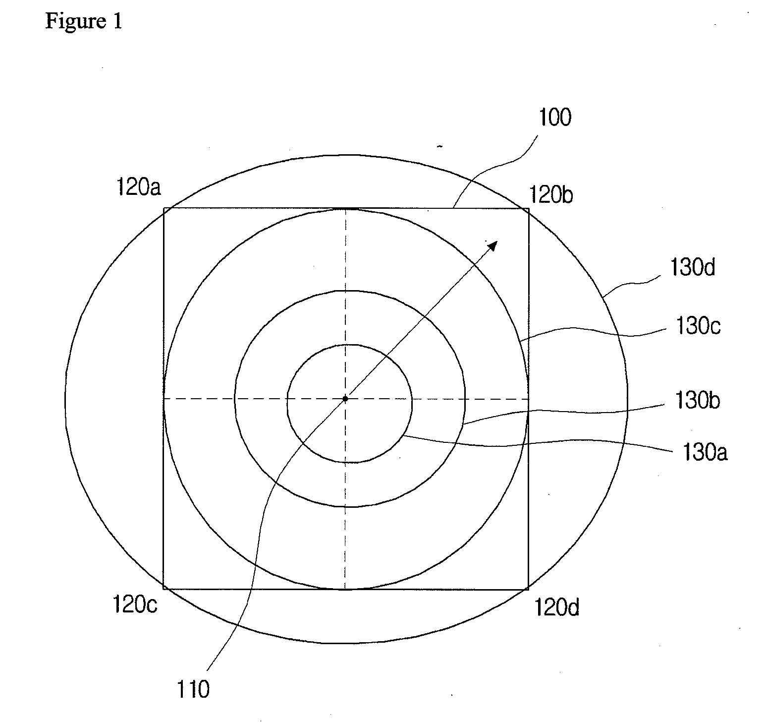
[0016]To solve the above problems, according to another aspect of the present invention, there can be provided an image noise reduction apparatus differentially reducing a noise of an image according to an area of the image. The image noise reduction apparatus can include a filter area selecting unit, selecting a filter area including a plurality of adjacent pixels based on an object pixel; and a noise reducing unit, reducing a noise of pixel data of the object pixel by using pixel data of the plurality of adjacent pixels in the filter area, whereas the noise reducing unit determines each weight of the plurality of adjacent pixels in the filter area according to the distance between the object pixel and a center pixel of the image. Here, it is possible that the wider the distance between the object pixel and the center pixel is, the more similar each weight of the adjacent pixels is.
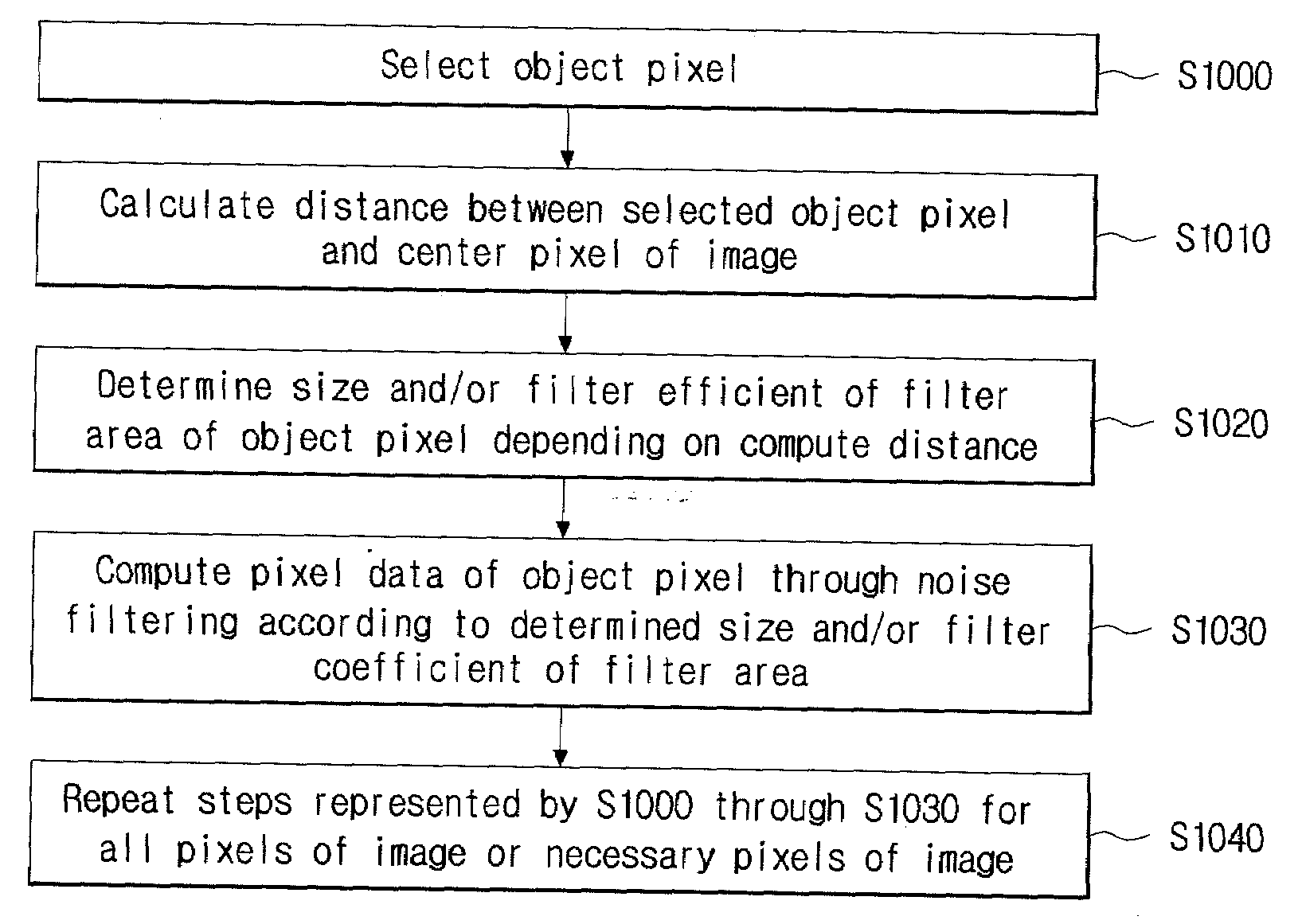
[0020]To solve the above problems, according to another aspect of the present invention, there can be provided an image noise reduction method differentially reducing a noise of an image according to an area of the image. The image noise reduction method can include (a) selecting an object pixel, a noise of which is to be reduced, of the pixels of the image; (b) computing the distance between the object pixel and a center pixel of the image; (c) determining each weight of the plurality of adjacent pixels in the filter area according to the computed distance; and (d) computing pixel data of the object pixel by using pixel data of the plurality of adjacent pixels in the filter area, applied with each of the weights. Here, it is possible that the wider the distance between the object pixel and the center pixel is, the more similar each weight of the adjacent pixels is.
[0025]To solve the above problems, according to another aspect of the present invention, a recording medium tangibly embodying a program of instructions executable by a digital processing apparatus in order to decrease the difference of noise components between a center part and a surrounding part of an image, the recording medium being readable by the digital processing apparatus, there can be the recording medium being recorded with a program performing a noise reduction method of the image.

Problems solved by technology

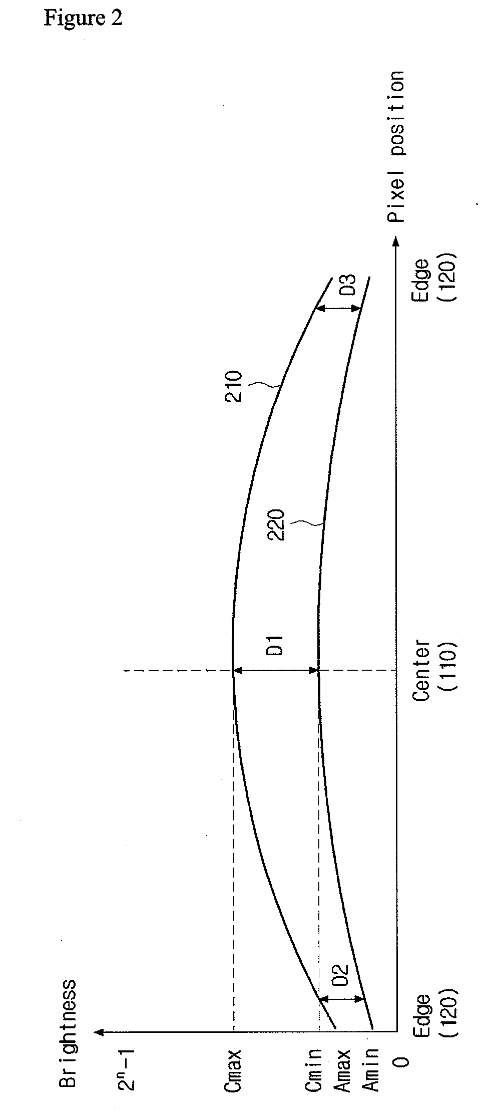
Although an image has different features per each area, the same setting generally applied to one image frame make it difficult to efficiently express the features of the image.
However, in this case, the noise component is amplified together in the surrounding part having the edge pixel 120, to thereby lower the resolution in the surrounding parts of the image 100 and deteriorate the quality of the image 100.

Method used


Image

  • Image noise reduction apparatus and method, recorded medium recorded the program performing it
  • Image noise reduction apparatus and method, recorded medium recorded the program performing it
  • Image noise reduction apparatus and method, recorded medium recorded the program performing it

Examples


Embodiment Construction

[0035]Hereinafter, some embodiments of an image noise reduction apparatus and a method thereof, and a recoding medium recorded with a program performing the method in accordance with the present invention will be described in detail with reference to the accompanying drawings. Throughout the description of the present invention, when describing a certain technology is determined to evade the point of the present invention, the pertinent detailed description will be omitted. Terms (e.g. “first” and “second”) used in this description merely are identification for successively identifying identical or similar elements.

[0036]FIG. 4 is a block diagram illustrating a noise reduction apparatus in accordance with an embodiment of the present invention, and FIG. 5 and FIG. 6 illustrate the size of a filter area depending on the position of a pixel in accordance with an embodiment of the present invention. FIG. 7 and FIG. 8 illustrate the change of filter coefficients of a filter area dependi...


PUM


Abstract

An apparatus and a method of reducing a noise component existed in a surrounding part of an image photographed in an image sensor. According to an aspect of the present invention, an apparatus differentially reducing a noise of an image according to an area of the image includes a filter area selecting unit, selecting a filter area including a plurality of adjacent pixels based on an object pixel; and a noise reducing unit, computing pixel data of the object by using pixel data of the plurality of adjacent pixels in the filter area, whereas the filter area selecting unit determines the size of the filter area according to the distance between the object pixel and a center pixel of the image. The present invention can prevent a noise component of a surrounding part from being amplified by using a different low pass filter in a center part and a surrounding part of an image and can acquire the resolution and quality of the desired image.

Description

CROSS-REFERENCE TO RELATED APPLICATIONS[0001]This application claims foreign priority benefits under 35 U.S.C. sctn. 119(a)-(d) to PCT / KR2007 / 003848, filed Aug. 10, 2007, which is hereby incorporated by reference in its entirety.BACKGROUND[0002]1. Technical Field[0003]The present invention relates to an image sensor, more specifically, an apparatus and a method of reducing a noise component in the surroundings of an image photographed by an image sensor.[0004]2. Description of the Related Art[0005]An image sensor refers to the semiconductor device converting an optical image into an electric signal. Portable apparatuses (e.g. digital cameras and mobile communication terminal) having image sensors are now developed and on sale. The image sensor consists of the arrays of small photo diodes, which are called pixel or photosite. The pixels themselves typically do not extract color from light. The pixels merely convert photos, provided from a wide spectrum band, into electrons. To write ...

Claims


Application Information

Patent Timeline
IPC IPC(8): G06K9/40H04N5/217H04N5/357
CPCH04N1/409H04N5/3572H04N5/357H04N25/61H04N25/60
Inventor NOH, YO-HWAN
Owner MTEKVISION CO LTD
Learn More