Connection element for connecting sheet piles to carrier elements as well as a combination sheet pile wall with such connection elements

a technology of connecting elements and carrier elements, which is applied in the direction of couplings, rod connections, manufacturing tools, etc., can solve the problems of insufficient evasive movement of sheet pile interlocks, inability to withstand forces of conjugated sheet pile walls, and inability to provide sheet pile interlocks for the protection of coastal sections. , to achieve the effect of high stress, high stress, and sufficient stiffness of hook strips

Active Publication Date: 2009-07-30
SHEET PILE LLC
View PDF13 Cites 19 Cited by
  • Summary
  • Abstract
  • Description
  • Claims
  • Application Information

AI Technical Summary

Benefits of technology

[0013]To ensure sufficient stiffness of the hook strip, in one preferred embodiment of the connection element according to the invention, the first support surface transitions into a first outer surface of the hook section that points outward, whereby the plane in which the first outer surface extends runs at an angle of at least 90° in a cross-sectional view, while the first outer surface transitions under formation of a radius into the second outer surface of the transition section that points outward. This ensures that tensions acting at the hook section of the hook strip are uniformly diverted to the base strip by the transition section.
[0014]In a particularly preferred advancement of this preferred embodiment, the angle between the first support surface and the first outer surface is in a range of 100 to 110°. This design feature achieves additional thickening and thus stiffening of the transition between the hook section and the transition section such that the hook strip can withstand extremely high stresses. At the same time, the arising tensions are diverted effectively here as well, and that without interference to the transition section and thus to the bases strip by the uniform and rounded contour of the outer surface.

Problems solved by technology

However, the use of the known combination sheet pile walls in coastal sections of the arctic circle poses problems because, in addition to the typical forces acting on the combination sheet pile walls, in particular on the sheet pile interlocks and the engaged interlocking profiles of the connection elements, extreme forces caused by pack ice are present during the winter months.
The past has shown that the combination sheet pile walls that were provided for the protection of these coastal sections were not able to withstand the forces caused in particular by the pack ice.
One reason for this may be that the sheet pile interlocks are not able to make sufficient evasive movements in the interlocking profiles of the connection elements.

Method used


Image

  • Connection element for connecting sheet piles to carrier elements as well as a combination sheet pile wall with such connection elements
  • Connection element for connecting sheet piles to carrier elements as well as a combination sheet pile wall with such connection elements
  • Connection element for connecting sheet piles to carrier elements as well as a combination sheet pile wall with such connection elements

Examples


Embodiment Construction

[0037]The preferred embodiments of the present invention will now be described with reference to FIGS. 1-9 of the drawings. Identical elements in the various figures are designated with the same reference numerals.

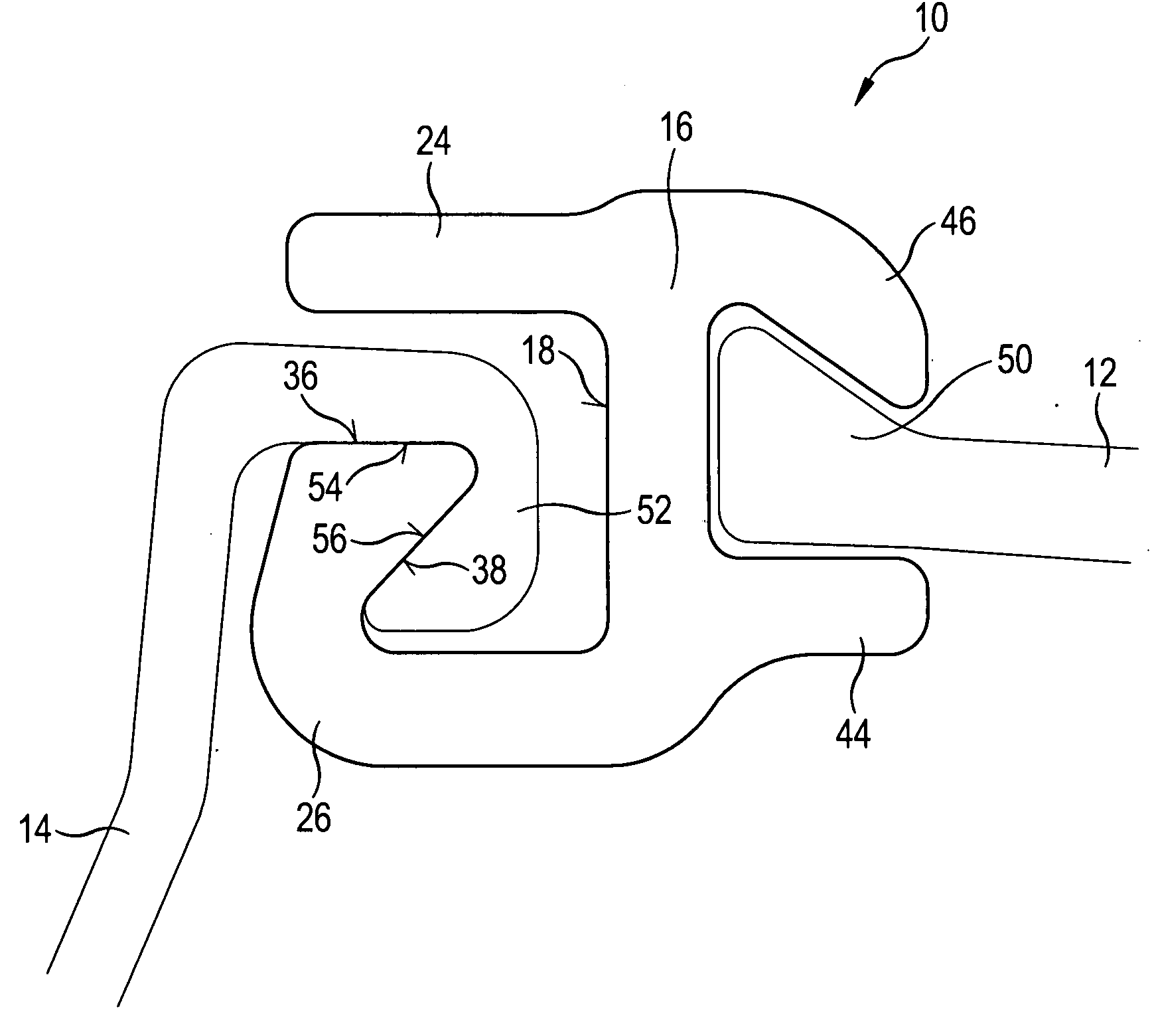
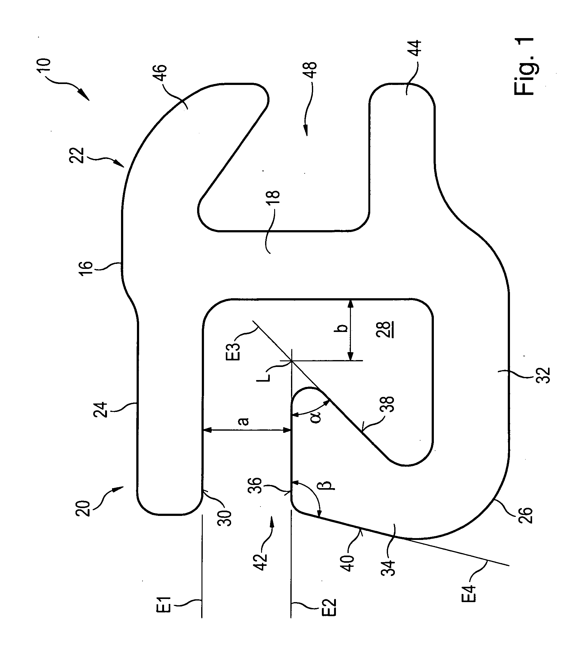
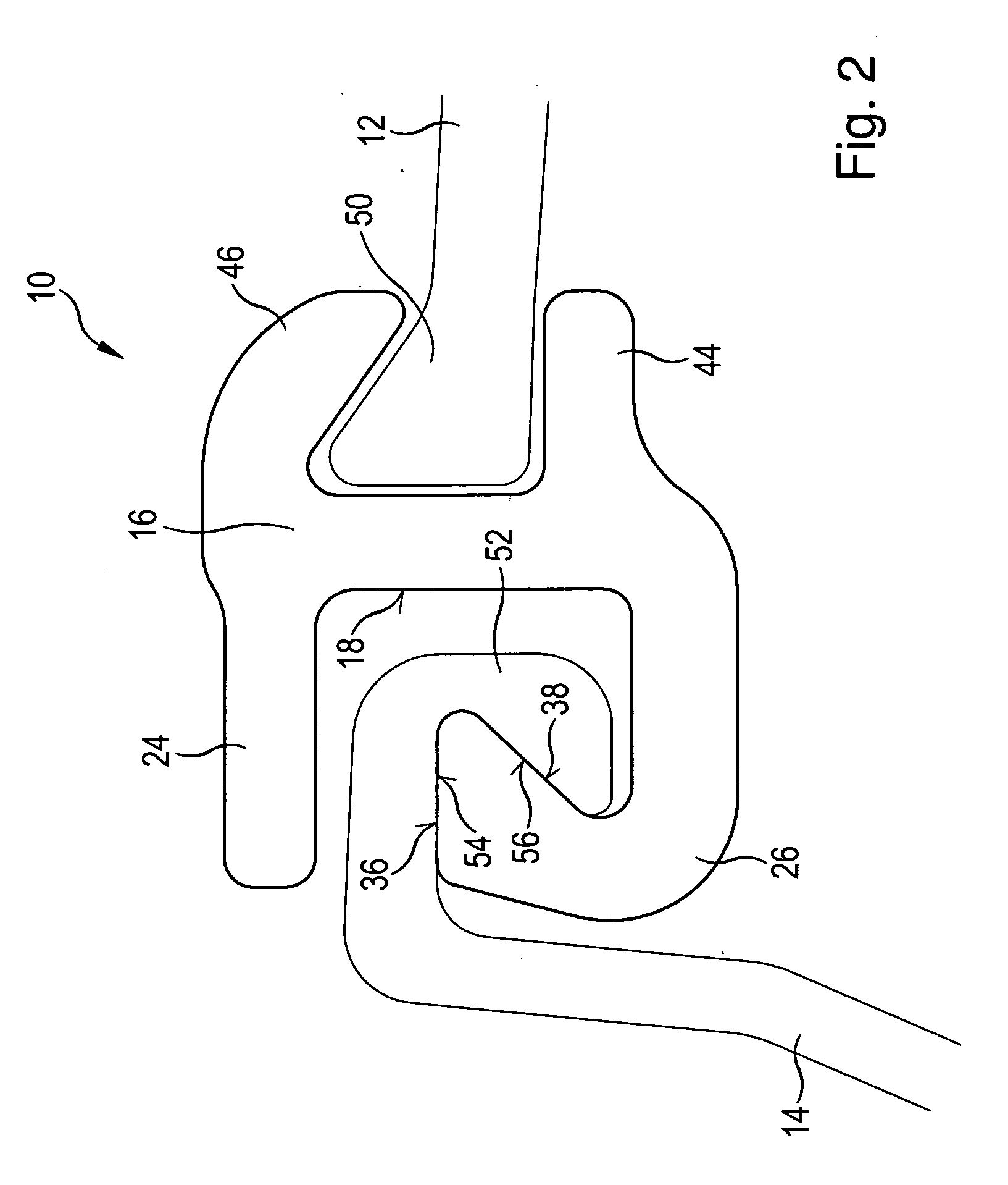
[0038]FIGS. 1 to 3 show a first exemplary embodiment of a connection element 10 according to the invention that is used to connect a carrier element 12 to a sheet pile 14 (cf. FIGS. 2 and 3). The connection element 10 exhibits a central base strip 16 with a straight, plane central section 18. An interlock profile 20 for coupling to the sheet pile 14 is formed at the flat side of the central section 18 shown in FIG. 1 on the left. An attachment profile 22 for connecting to the carrier element 12 is formed at the second flat side of the central section 18 that faces away.

[0039]The interlock profile 20 is formed by a support strip 24 and a hook strip 26, which together with the central section 18 of the base strip 16 define a lock chamber 28.

[0040]Beginning at the longitudina...


PUM


Abstract

A connection element for connecting a sheet pile to a carrier element, with a base strip (16) to be fastened to a carrier element (14), is provided with an interlock profile (20) for engaging the sheet pile (14). The interlock profile (20) exhibits a lock chamber (28) that is defined by the base strip (16), a support strip (24) that protrudes from the base strip (16) and a hook strip (26) that protrudes from the base strip (16), whereby the hook strip (16) exhibits a straight extending transition section (32) protruding from the base strip (16) and a hook section (34) that follows said transition section and points in the direction of the support strip (34). The hook section exhibits a first support surface (26) that faces an inner surface (30) of the support strip (24), whereby the first support surface (36) and at least that section of the inner surface (30) of the support strip (24) that directly faces the first support surface (26) are located in parallel converging planes (E1, E2) and together define the jaw (42) of the lock chamber (28). The first support surface (36) transitions under an acute angle (α) into a second support surface (38) that defines the lock chamber (28).

Description

BACKGROUND OF THE INVENTION[0001]The invention concerns a connection element with a uniform cross-section for connecting a sheet pile to a carrier element. In addition, the invention concerns a combination sheet pile wall with such a connection element.[0002]Connection elements of the type mentioned above are used to erect so-called combination sheet pile walls. A combination sheet pile wall is an arrangement of carrier elements and sheet piles where at least one sheet pile is placed between each of two carriers, for example I-beams. The sheet pile is coupled with the carrier element using the connection element named above.[0003]For connecting the connection element to the carrier element, the base strip of the connection element is attached at the carrier element. If the carrier element is provided with fastening sections such as flanges, then the base strip is equipped with a suitable attachment profile that is used to slide the base strip onto the fastening section of the carrie...

Claims


Application Information

Patent Timeline
Patent Type & Authority Applications(United States)
IPC IPC(8): E02D5/08E02D5/02
CPCE02D5/08Y10T24/34Y10T403/5706
Inventor HEINDL, RICHARD
Owner SHEET PILE LLC
Why Eureka
Try Eureka