Highly Adjustable Lumbar Support And Methods

a lumbar support, high-adjustable technology, applied in the field of lumbar supports, can solve the problems of users not fully tightening the strap, body braces are difficult to appropriately position and fasten, and willis, however, fails to contour to body shapes of different shapes and sizes, so as to increase the mechanical advantage ratio of the mechanism and increase the force of adjustment

Inactive Publication Date: 2009-07-30
CARSAR
View PDF17 Cites 79 Cited by
  • Summary
  • Abstract
  • Description
  • Claims
  • Application Information

AI Technical Summary

Benefits of technology

[0015]A back support piece could also be used that places an anterior force on the lumbar region of the wearer, and could be shaped and disposed to not only contact a large area of the wearer's lumbar region, but provide lordosis support for a sacrum of the wearer. Preferably, an advantaged adjustment mechanism is used to adjust the shape and size of the back support piece. The advantaged adjustment mechanism could be a series of pulleys, gears, levers, screws, or combinations thereof to provide more force to the adjustment. Preferably, the advantaged adjustment mechanism is mechanically advantaged more than 2:1, and is more preferably mechanically advantaged at 4:1 or more. Additional pulleys or longer levers could easily increase the mechanical advantage ratio of the mechanism. The back piece could be rigid, or could have rigid components with joints that bend and flex depending on how the adjustment mechanism is manipulated. Preferably, multiple adjustment mechanisms adjust the shape and size of the back support. For example, an upper cord guide could conform the upper 3 inches (7.62 cm) of the back support to a lumbar-thoracic area, while a lower cord guide could conform the lower 3 inches (7.62 cm) of the back support to a lumbar-sacral area.
[0016]Preferably the adjustment mechanisms tighten when a wearer pulls a tightening element forward, so that tightening the adjustment mechanisms is easy for a wearer. For example, a side panel with a fold-back mechanism preferably folds forward, and a back panel with an advantaged pulley adjustment mechanism has strings that tighten when pulled forward. The tightening elements preferably have a fastener, for example Velcro™ hooks and loops, that mate with a side of the body brace.

Problems solved by technology

However, for many users body braces are difficult to appropriately position and fasten.
The awkward angle of the strap prevents users from fully tightening the strap themselves and requires a third party to assist in the tightening process.
Willis, however, fails to contour to body shapes of different shapes and sizes, for example differently shaped hips and different lordotic curves.

Method used


Image

  • Highly Adjustable Lumbar Support And Methods
  • Highly Adjustable Lumbar Support And Methods
  • Highly Adjustable Lumbar Support And Methods

Examples


Embodiment Construction

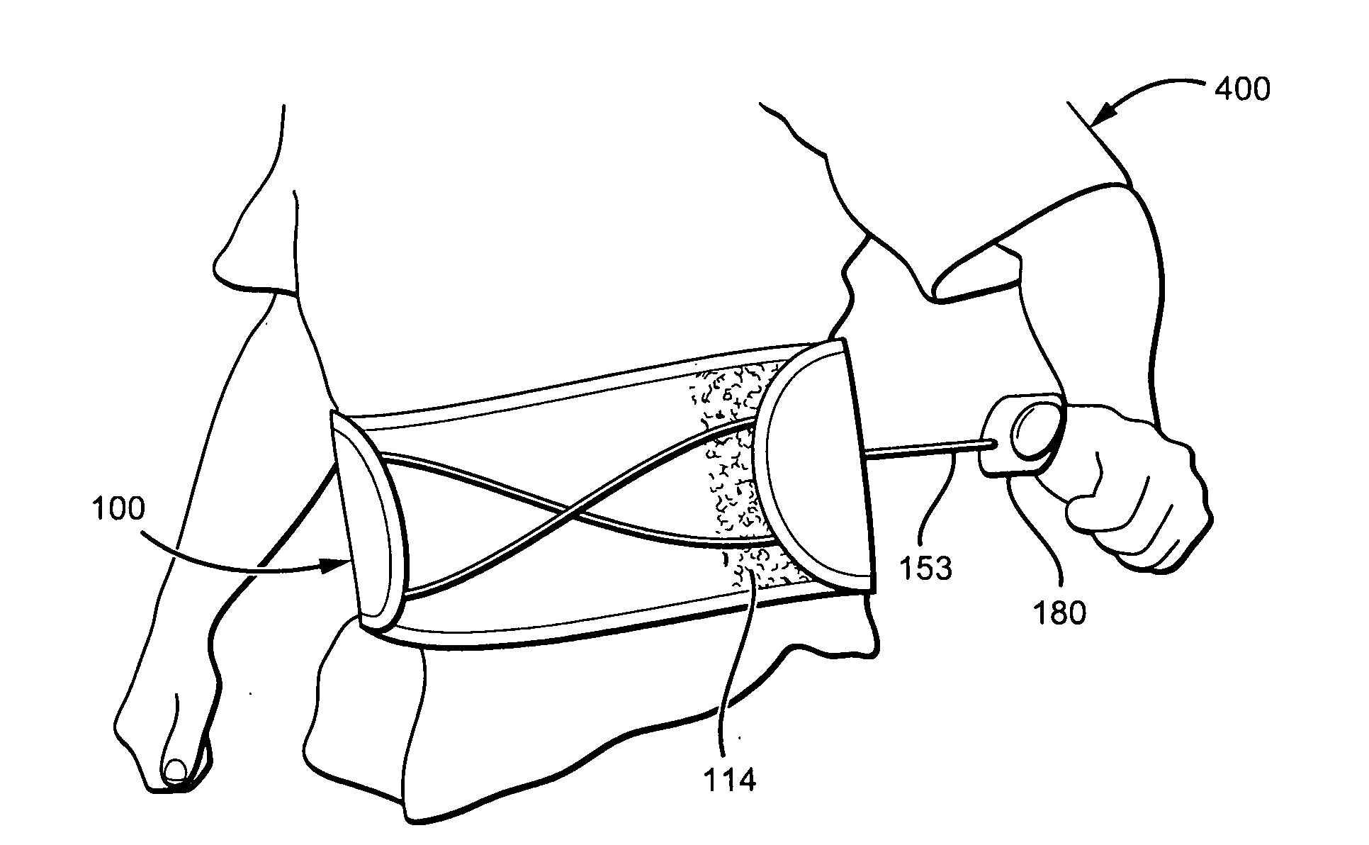
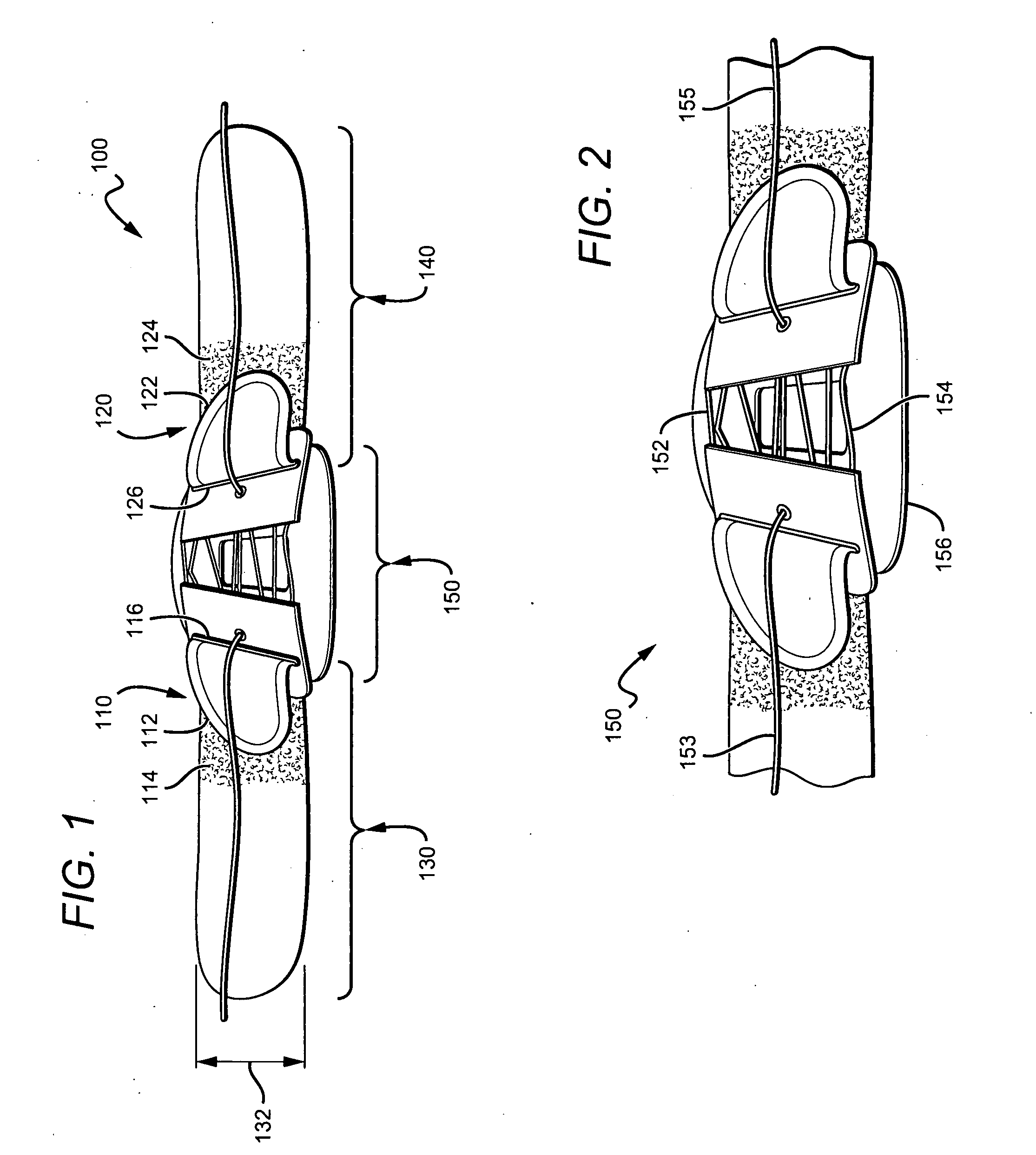
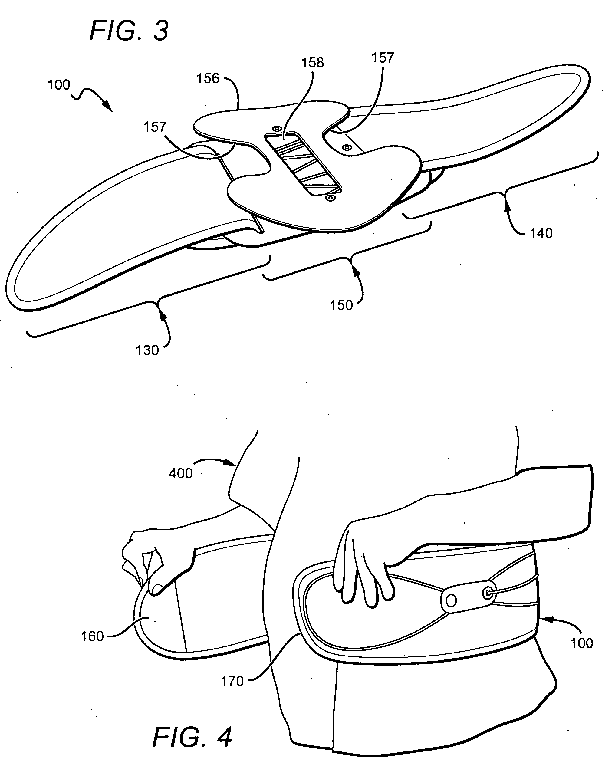
[0026]Referring to the drawings to illustrate preferred embodiments, but not for the purpose of limiting the invention, FIG. 1, illustrates one embodiment of a body brace 100 with a first adjustment mechanism 110, a second adjustment mechanism 120, a left side piece 130, a right side piece 140, and a back piece 150.

[0027]First adjustment mechanism 110 is a fold-back adjustment mechanism that adjusts an effective length of left side piece 130. As used herein, an “effective length” is the length of the side piece that acts as the circumference of the body brace when the brace is worn about a wearer. As best seen in FIG. 1, a hook portion 112 of left side piece 130 threads through slot 116 of back piece 150. The hook portion 112 then folds back over a loop portion 114 of left side piece 130 which then mates with loop portion 114 to form a hook and loop fastener. Such hook and loop fasteners are commonly referred to in the art as Velcro™ fastening.

[0028]Preferably, the hook portion cove...


PUM


Abstract

A body brace for a wearer has a combination of adjustment mechanisms and fasteners to help fit the body brace to a wearer. A wearer first fastens the body brace about his abdomen and lumbar regions to generally fit the body brace around the wearer's waist. The wearer then adjusts one set of adjustment mechanisms that adjust an upper and lower circumference of the brace to allow the brace to fit both straight and pear-shaped bodies. Lastly, the wearer adjusts a second set of adjustment mechanisms that tighten a rear panel of the body brace against a lumbar region of the wearer. Preferably, the adjustment mechanism that is used to tighten the rear panel is an advantaged adjustment mechanism to allow for fine-tuning and a snug fit.

Description

[0001]This application is a continuation-in-part of non-provisional application Ser. No. 10 / 977,726 filed Mar. 2, 2005, which is a divisional of non-provisional application Ser. No. 10 / 440,525, filed May 19, 2003.FIELD OF THE INVENTION[0002]The field of the invention is lumbar supports.BACKGROUND[0003]Orthotic devices are typically provided for partial or substantial immobilization of the torso to stabilize the back. Some orthotic devices are back braces that fit around the torso around the lumbar area. When worn properly, a body brace can lend additional support to the abdomen and the spinal column to achieve spinal stability. However, for many users body braces are difficult to appropriately position and fasten. For example, U.S. Pat. No. 4,640,269 to Goins provides a back brace that is tightened around the body by threading a Velcro strap through a loop and pulling the strap backwards towards the user's posterior. The awkward angle of the strap prevents users from fully tightenin...

Claims


Application Information

Patent Timeline
Patent Type & Authority Applications(United States)
IPC IPC(8): A61F5/00
CPCA61F5/03A61F5/028
Inventor GARTH, GEOFFREY C.ROMO, ALBERT VICTORBURKE, STEVEN RICHARDPEREZ, JOEL
Owner CARSAR
Why Eureka
Try Eureka