Gas vent valve assembly

Inactive Publication Date: 2009-07-30
SMITHS MEDICAL ASD INC
View PDF7 Cites 30 Cited by
  • Summary
  • Abstract
  • Description
  • Claims
  • Application Information

AI Technical Summary

Benefits of technology

[0006]The gas vent valve assembly of the present invention is designed and adapted for use in an intravenous tube (IV) set that is disposable after use. The IV set, which is connected to a physiological fluid heater, such as for example any one of the systems H-1025, H-1200 and H-1000 High Flow Blood and

Problems solved by technology

However, when an upper seal is used in conjunction with a hydrophobic membrane, the usefu

Method used


Image

  • Gas vent valve assembly
  • Gas vent valve assembly
  • Gas vent valve assembly

Examples


Example

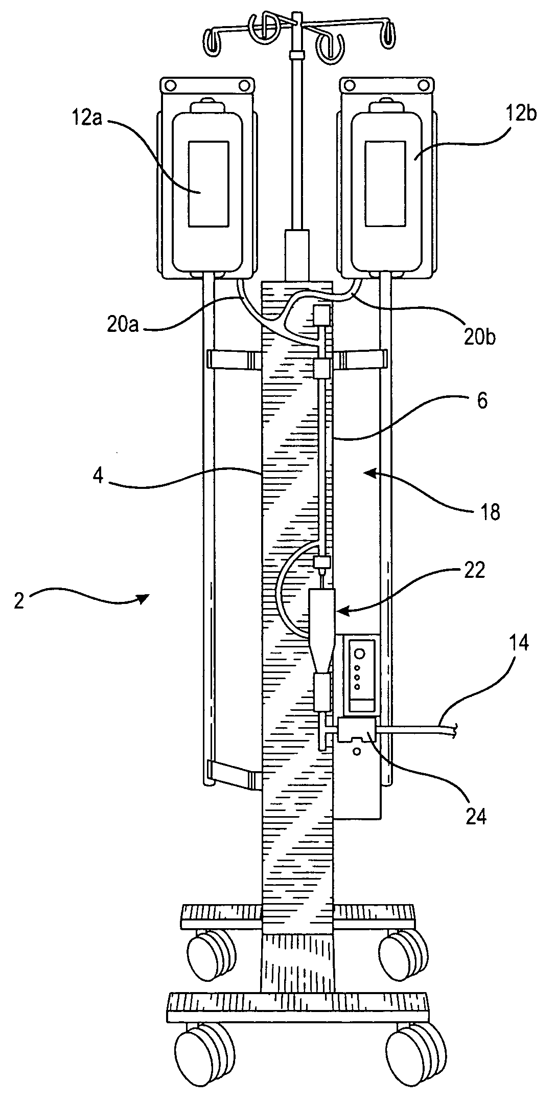
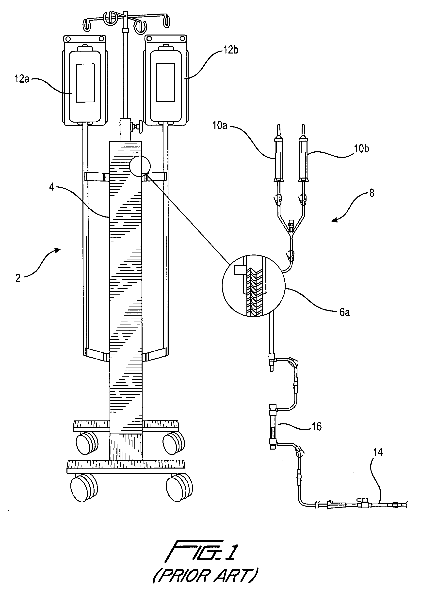
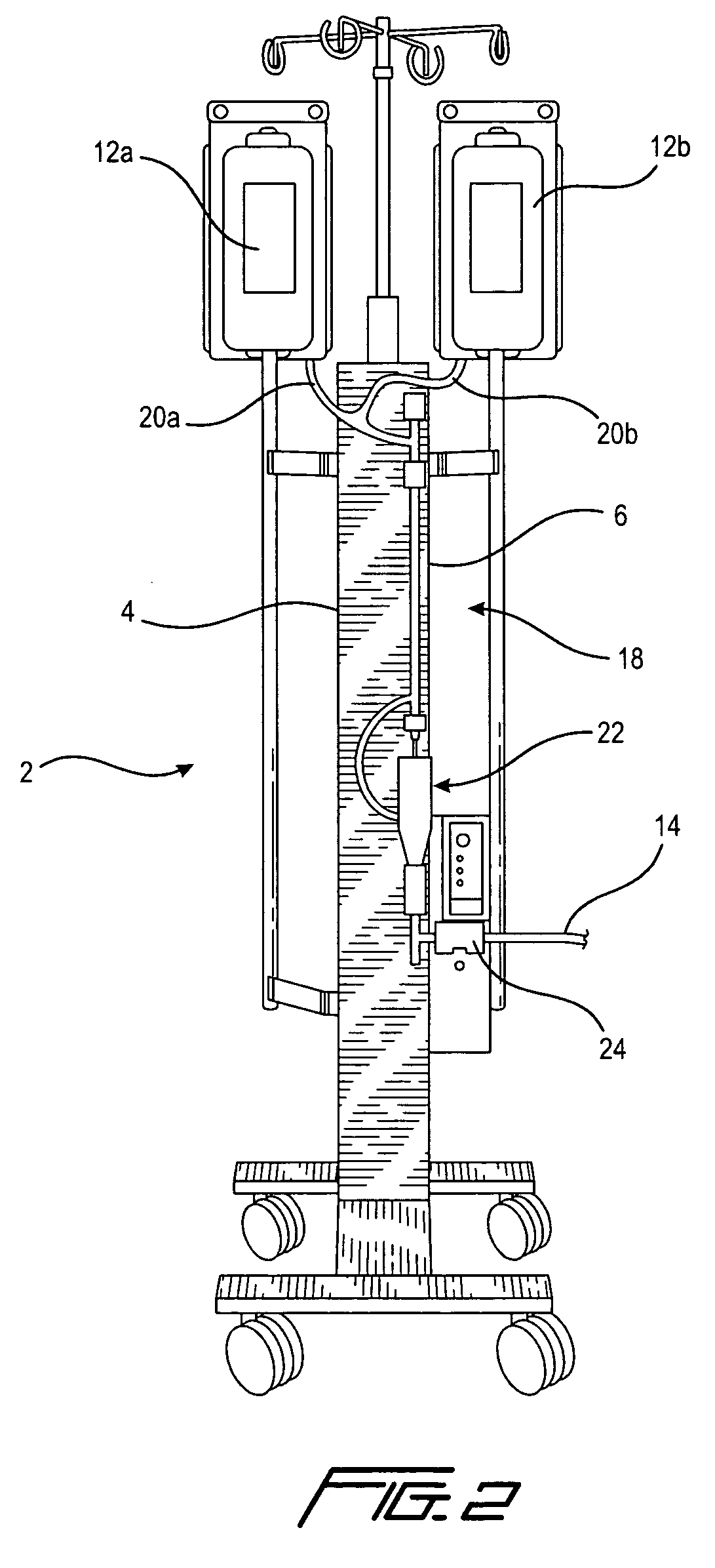
[0023]With reference to FIG. 1, a prior art fluid warmer, such as for example the System 1025 manufactured by the assignee of the instant application, is shown. The fluid warmer is designated 2 and includes a central portion 4 that has a heater therein for fluidly heating a heat exchanger 6, a portion of which is shown in the exploded view 6a. The heat exchanger 6 is a part of a fluid transfer disposable set 8, for example an intravenous (IV) tube set, that includes bag spikes 10a and 10b that are used to connect to storage bags 12a and 12b, respectively. The storage bags 12a and 12b may be referred to as fluid reservoirs that store cellular or physiological fluids such as for example blood, saline and other well known fluids for infusion into a patient. As the fluid from the fluid reservoir flows through heat exchanger 6, it is heated. This heated fluid is introduced or administered to a patient as an infusate, by means of a tube 14 that has a conventional luer end for connection t...


PUM


Abstract

A gas vent valve assembly may be attached or incorporated to a disposable fluid transfer set used with a fluid warmer to administer an infusate to a patient. The gas vent valve assembly has a housing having a fluid inlet, a gas outlet and a fluid outlet. The gas outlet is located at the top of the housing while the fluid outlet is located at the bottom of the housing. The fluid inlet is located at a side lower portion of the housing. Inside the housing is an actuator float that has an upper seal and a lower seal. The dimension of the float relative to the chamber of the housing is such that the float is freely movable within the housing to an upper position whereby its upper seal closes the gas outlet while the fluid outlet is opened, and to a lower position whereby its lower seal closes the fluid outlet and the gas outlet is opened. The movement of the float is dependent on the respective amounts of air and fluid in the housing, and the buoyancy of the float relative to the fluid in the housing. When a predetermined volume of air gets inside the housing, the float sinks to its lower position to close the fluid outlet and open the gas outlet, so that the air inside the housing is vented to atmosphere while fluid is prevented from being output to the patient. When the amount of gas in the chamber has been reduced to a given volume, with a corresponding increase in the amount of fluid in the housing, the float is raised to open the fluid outlet, thereby enabling the fluid inside the housing to be output to the patient. At that time, the gas outlet is shut to prevent any reverse inflow of air into the housing.

Description

FIELD OF THE INVENTION[0001]The present invention relates to a device for eliminating gases or air that may be trapped within an intravenous (IV) tube set used to provide physiological or cellular fluids to a patient.BACKGROUND OF THE INVENTION[0002]When physiological or cellular fluids are administered to a patient, it is imperative that foreign particles and gas bubbles or air emboli that may be trapped in the fluids be removed. In the prior art, these fluids are passed through a filter before being administered to the patient.[0003]One prior art filter is disclosed in U.S. Pat. No. 4,662,906. This filter includes a structure that first separates the gas from the fluid by introducing a vortex flow into the fluid. The gas bubbles that are separated from the fluid are moved into a chamber that is formed in part by a hydrophobic membrane, so that the gas exits to the atmosphere through the membrane. The fluid is then passed through a defoaming sponge, treated with an anti-foaming age...

Claims


Application Information

Patent Timeline
IPC IPC(8): A61M1/00A61F7/00
CPCA61F7/0085A61M5/40A61M5/385A61M5/36Y10T137/6416
Inventor ANDERSEN, ERICROBERT, RENESEARLE, GARYWALDRON, VINCENT
Owner SMITHS MEDICAL ASD INC
Why Eureka
Try Eureka