Personal Grooming Device Handle and Method for Making the Same

Inactive Publication Date: 2009-08-06
THE GILLETTE CO
View PDF10 Cites 36 Cited by
  • Summary
  • Abstract
  • Description
  • Claims
  • Application Information

AI Technical Summary

Benefits of technology

[0009]Features of the present invention may have one or more of the following advantages. The cross-sections of the three component parts allow for faster cycle times and, thus lower manufacturing costs over

Problems solved by technology

While disposable personal grooming devices are more price sensitive than so-called “system” devices (e.g., a safety razor shaving system h

Method used


Image

  • Personal Grooming Device Handle and Method for Making the Same
  • Personal Grooming Device Handle and Method for Making the Same
  • Personal Grooming Device Handle and Method for Making the Same

Examples


Embodiment Construction

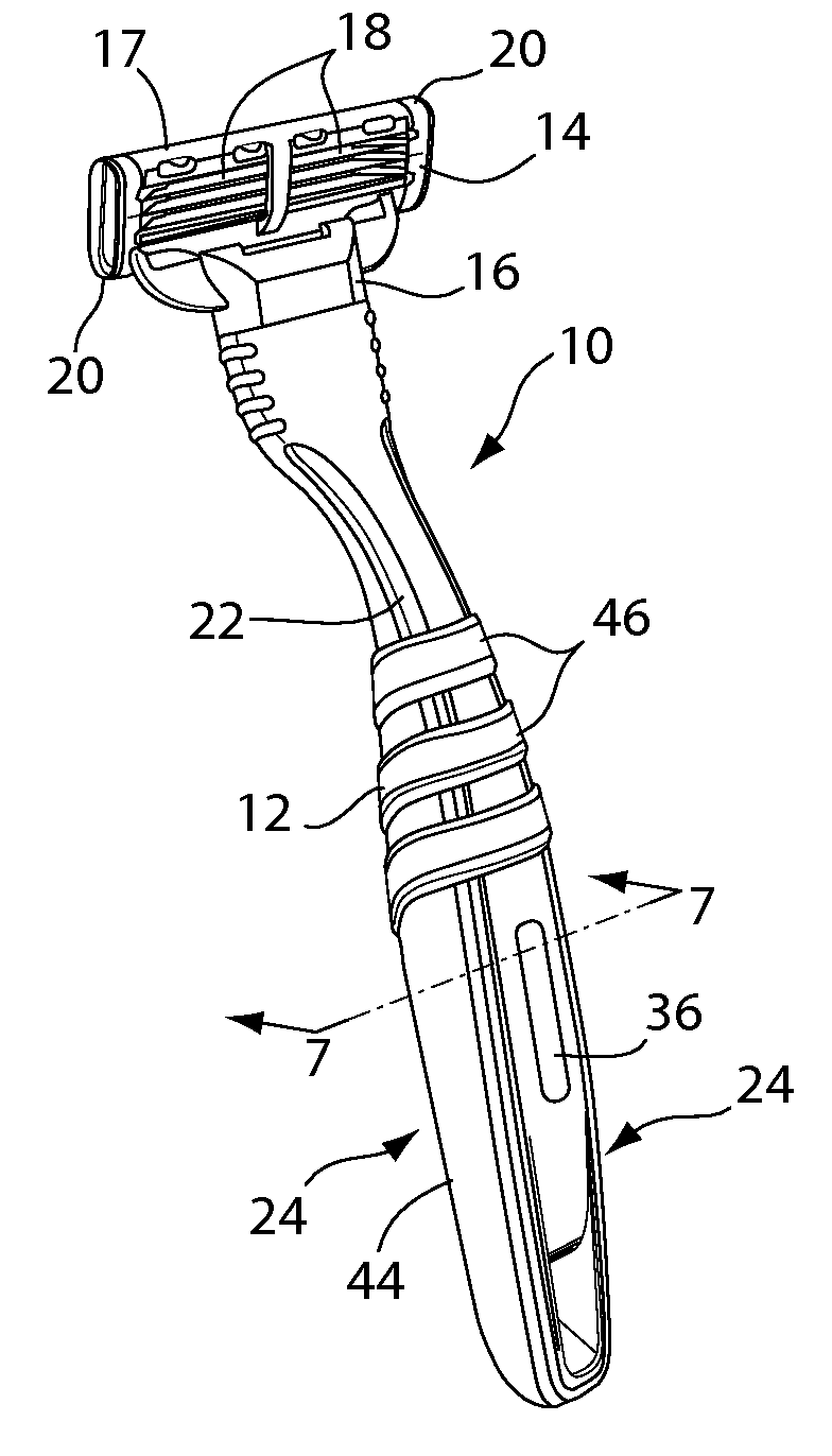
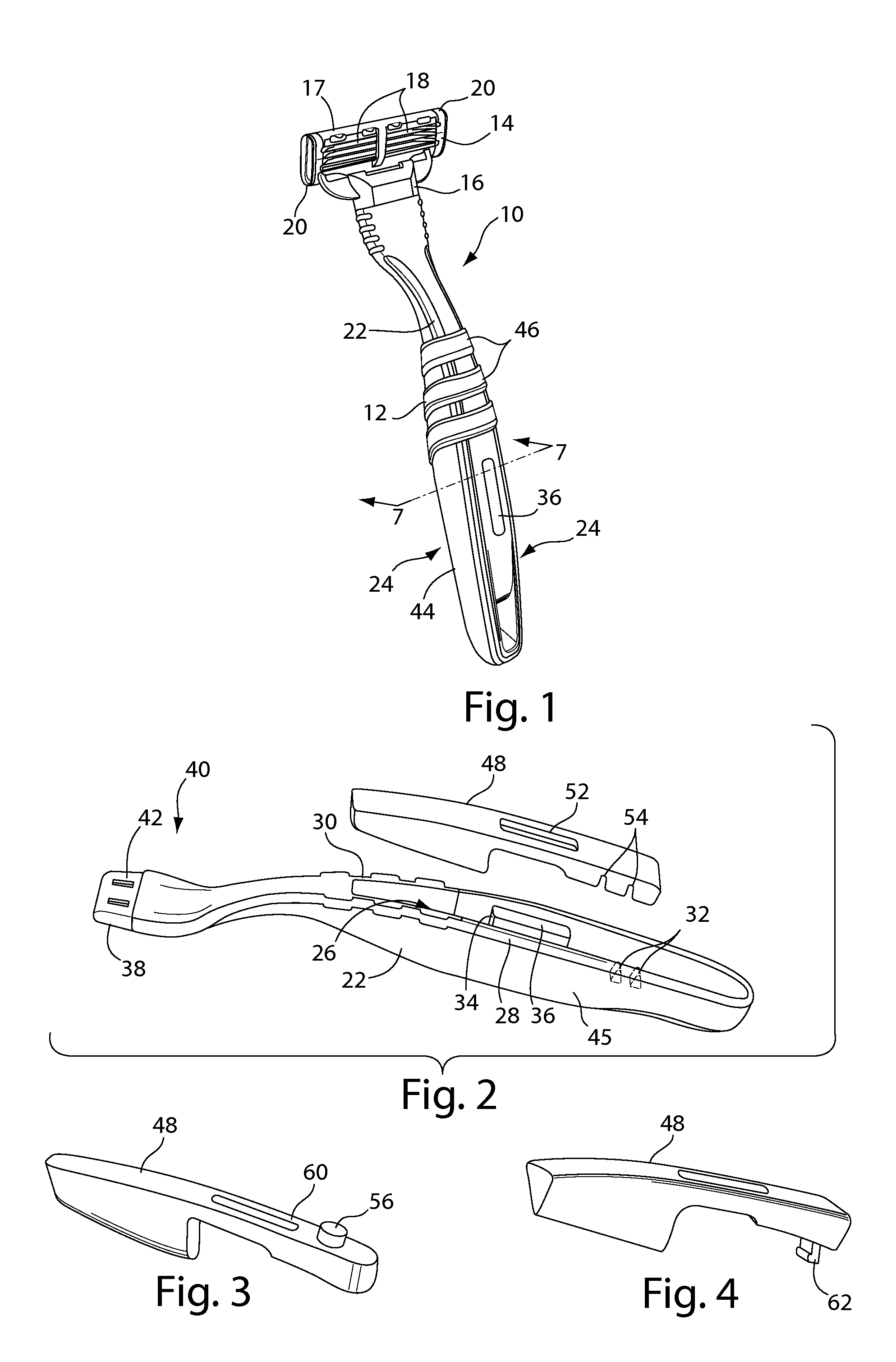
[0018]Referring to FIGS. 1 and 2, in some examples, safety razor 10 includes a handle 12 pivotally joined to a blade unit 14 by a connecting member 16. Blade unit 14 includes a plastic housing 17 and three blades 18 each with an elongated sharp cutting edge between a guard at the front of the housing and a cap with a lubricating strip at the rear of the housing and retained by clips 20. In other examples, two, four, five, or more blades could be included. In one example, blade unit 14 is similar to that of the Mach III razor, sold by The Gillette Company.

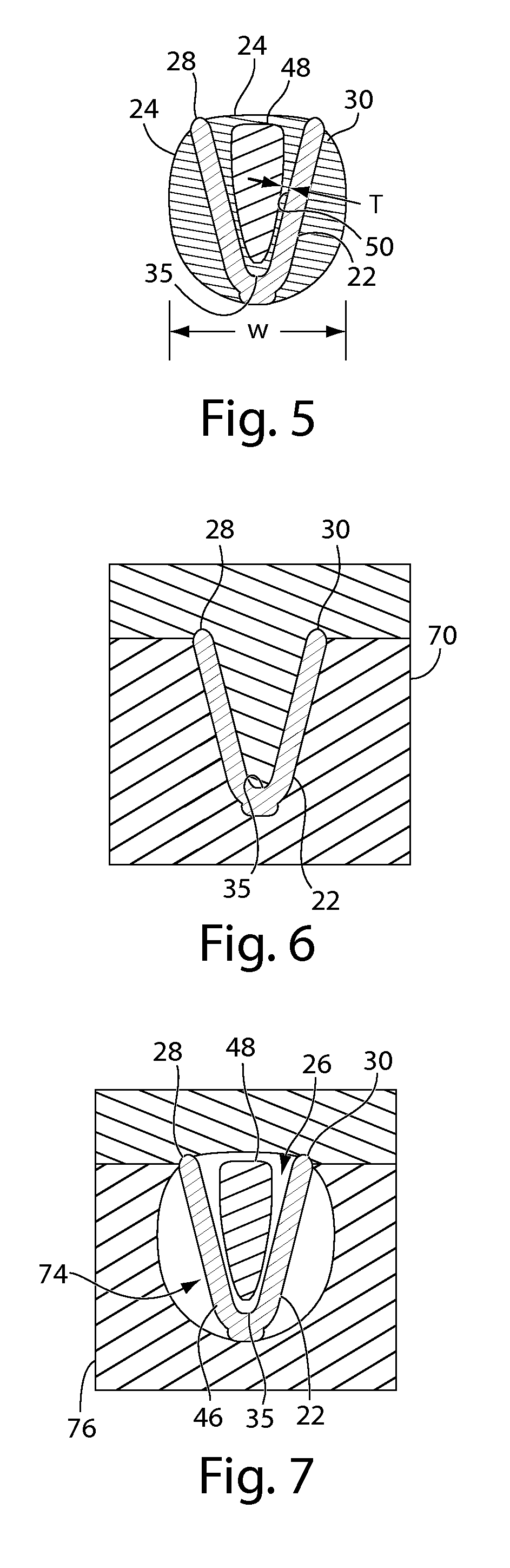
[0019]Handle 12 has a core portion 22 at least partially enclosed by a grip portion 24. Generally, core portion 22 may have a substantially consistent cross-section for good plastic flow, filling, and cooling during molding, as is understood in the art. In some examples, core portion 22 has a channel 26 extending along its length and formed by walls 28 and 30. One or more ribs 32 (shown in broken line in FIG. 2) may extend between w...


PUM


Abstract

A method of manufacturing a handle for a personal grooming device includes forming a substrate portion of a first material. The substrate portion has first and second walls forming a channel extending along a long axis of the substrate portion. An insert member is formed separate from the substrate portion and disposed within the channel. A grip portion of a second material is formed on the substrate portion. The second material substantially encases the insert member.

Description

CROSS REFERENCE TO RELATED APPLICATIONS[0001]This application claims priority under 35 U.S.C. §119(e) from U.S. Provisional Patent Application Ser. No. 61 / 025,998, filed Feb. 4, 2008.FIELD OF THE INVENTION[0002]This application relates to handles for personal grooming devices and methods of manufacturing the same.BACKGROUND OF THE INVENTION[0003]Handles for personal grooming devices are well known. Some device handles are formed by a “two-color” injection molding process combining a relatively rigid material with a relatively flexible material. The combination of rigid and flexible materials may improve the ergonomics associated with such handles and provide an improved shaving experience over single material handles. Some personal grooming device handles have relatively large cross sections for improved handling and comfort while being used. Larger cross sections may require longer cycle times during molding to completely fill out the mold cavities and avoiding sinks in the handle ...

Claims


Application Information

Patent Timeline
IPC IPC(8): A46B5/02B29C45/14
CPCA46B5/02A46B2200/1066B25G1/00B26B21/528B26B21/522
Inventor PENNELL, EVAN KENTLEE, ALEJANDRO CARLOS
Owner THE GILLETTE CO
Why Eureka
Try Eureka