Layered scavenging carburetor

a carburetor and scavenging technology, applied in the field of carburetors, can solve the problems of lean fuel mixtures and air generated by arrangemen

Inactive Publication Date: 2009-08-06
WALBRO ENGINE MANAGEMENT
View PDF14 Cites 12 Cited by
  • Summary
  • Abstract
  • Description
  • Claims
  • Application Information

AI Technical Summary

Benefits of technology

[0005]One embodiment of a valve assembly for use in a carburetor may include a throttle valve and an air valve. The air valve has an air bore that may extend from a first open end to a second open end. The air valve may have a first cutout located at the first open end, and may have a second c...

Problems solved by technology

Some of these arrangements may not generate air and fuel mixtures that are lean for an idle operating condition, for startup, or for other low speed and low loa...

Method used


Image

  • Layered scavenging carburetor
  • Layered scavenging carburetor
  • Layered scavenging carburetor

Examples


Embodiment Construction

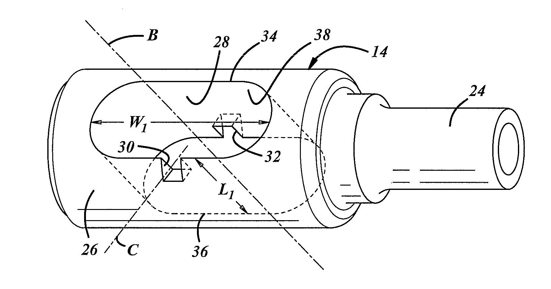
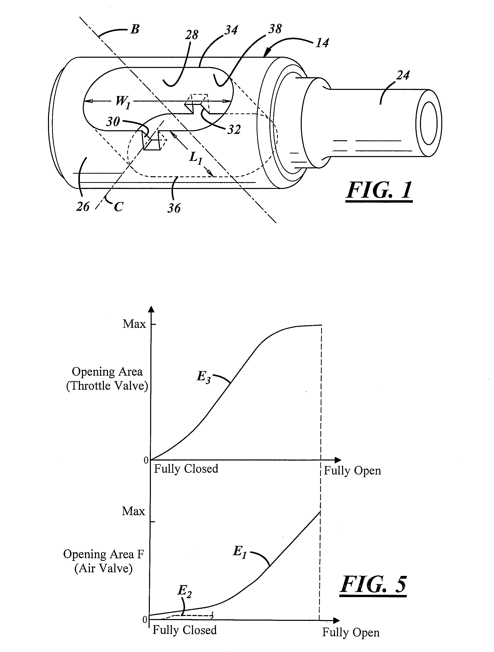
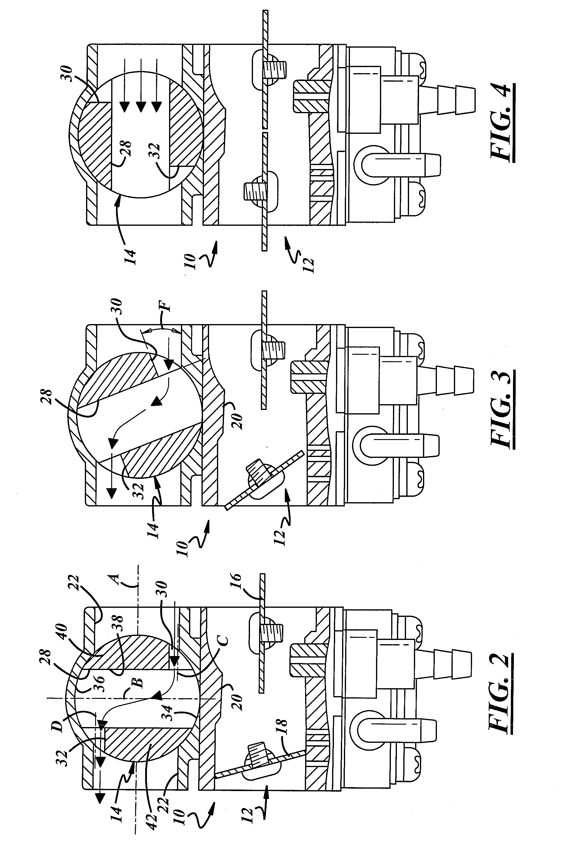
[0026]Referring in more detail to the drawings, FIGS. 1-5 show an exemplary embodiment of a valve assembly 10 that may be used in a carburetor (not fully shown) for a small two-stroke internal combustion engine such as those found in chainsaws, brushcutters, and the like. The valve assembly 10 may include a throttle valve 12 to regulate air and fuel mixture flow, and may include an air valve 14 to regulate scavenging airflow. The air valve 14 may be designed and constructed to continuously increase the amount of airflow that travels through the air valve from a fully closed position to a fully open position without a period of no increase of airflow and without decreasing the amount of airflow.

[0027]The carburetor mixes and supplies air and fuel to the internal combustion engine. The carburetor may be of the float (a.k.a., bowl) chamber type, diaphragm chamber type, or other type. The valve assembly 10 may regulate fluid-flow in the carburetor by permitting flow when the valve assem...


PUM


Abstract

A scavenging valve assembly is used in a carburetor. The valve assembly includes a throttle valve and a rotary air valve. The throttle valve opens and closes an air-fuel passage. The rotary air valve opens and closes an air passage and has one or more air bore(s). When the rotary air valve begins to rotate, airflow travels through the bore(s) and the size of an opening area that airflow travels through continuously increases in size.

Description

REFERENCE TO RELATED APPLICATION[0001]Applicants claim priority of Japanese Patent Application, Ser. No. 2008-026567, filed Feb. 6, 2008.FIELD OF THE INVENTION[0002]The present invention relates generally to carburetors, and more particularly to valves and valve assemblies used in carburetors.BACKGROUND OF THE INVENTION[0003]Two-stroke internal combustion engines such as those used in chainsaws, brushcutters, and the like, are often equipped with carburetors for mixing and supplying air and fuel to the engine. Some scavenging carburetor arrangements may have separate air-fuel passages and air passages that may help reduce, and often prevent, undesirable flow-through and fuel-loss through its exhaust. Some of these arrangements may not generate air and fuel mixtures that are lean for an idle operating condition, for startup, or for other low speed and low load operating conditions. And some of these arrangements may generate air and fuel mixtures that are too lean upon a rapid accele...

Claims


Application Information

Patent Timeline
IPC IPC(8): F16K5/00
CPCF02M9/12Y02T10/146F02M23/03Y02T10/12Y10T137/87161
Inventor AIHARA, TAMIODOUYAMA, YOSHIAKIOHGANE, SHINICHI
Owner WALBRO ENGINE MANAGEMENT
Why Eureka
Try Eureka