Wireless repeater with smart uplink

a repeater and wireless technology, applied in repeater/relay circuits, frequency-division multiplexes, transmission monitoring, etc., can solve the problems of repeater systems with significant uplink performance limits, repeater systems encounter further performance limits, limit the choice of repeater design and output capability, etc., to enhance wireless coverage for host base stations

Active Publication Date: 2009-08-06
INTEL CORP
View PDF15 Cites 69 Cited by
  • Summary
  • Abstract
  • Description
  • Claims
  • Application Information

AI Technical Summary

Benefits of technology

[0010]In a first embodiment of the present invention, a communication system for enhancing wireless coverage for a host base station is provided. The communication system includes a digital repeater receiving and providing time division multiplexed (TDM) communication signals (e.g. GSM and EDGE) between a host base station and a communication network for a plurality of RF channels, a digital filter for each of the plurality of RF channels, the filter being synchronized to the corresponding RF channel timing of the host base station, a delay buffer for each RF channel configured to provide a time delayed TDM signal for a power measurement on the RF channel, a power measurement unit, and a gain setting unit for each RF channel receiving the time delayed communication signal and power measurement for adjusting a gain setting on each RF channel.

Problems solved by technology

In all cases over the air repeater systems have significant uplink performance limits when finite power amplifier output capability is combined with input signals simultaneously spanning weak and strong signal levels.
Over the air repeater systems encounter further performance limits, for example, the Global System for Mobile Communication (GSM) signals utilize the frequency hopping mode of operation which in conjunction with dynamic range limits severely limits the choice in repeater design and output capability.
GSM repeaters, especially multi-carrier sub-band units, are confronted with the added challenge of the wide dynamic range differences due to concurrently amplifying signals from both near and far mobile units.
However, this approach is not cost effective to support a moderate or large number of simultaneous RF channels and may result in impractically sized product solutions.
However, the use of MCPAs on the uplink limits the useful gain range of these types of repeaters and tend to be limited to lower power applications.
Thus, the weak signals will not be able to communicate with the donor base station, which is equivalent to reducing the reverse link coverage range of the repeater.
Some repeaters may utilize digital processing of the RF signals but will still treat groups of RF channels as a single entity with the associated gain coupling limitations.
However, limiting the output level of the MCPA through gain changes still couples the effects due to strong signals to the weak signals.
This still does not address the limitations imposed by a shared MCPA at the output.
However, it takes a finite amount of time to detect the presence of a strong signal and during that time period the PA output will be overloaded.
Conversely, starting at low gain will require some time before a weak signal detection decision can be used to increase gain.
This is further complicated by the presence of frequency hopping which adds frequency uncertainty to the existing power versus time uncertainty.
Finally, none of the prior art addresses techniques to accommodate feedback cancellation operations and the presence of strong feedback signals at the input.

Method used


Image

  • Wireless repeater with smart uplink
  • Wireless repeater with smart uplink
  • Wireless repeater with smart uplink

Examples


Embodiment Construction

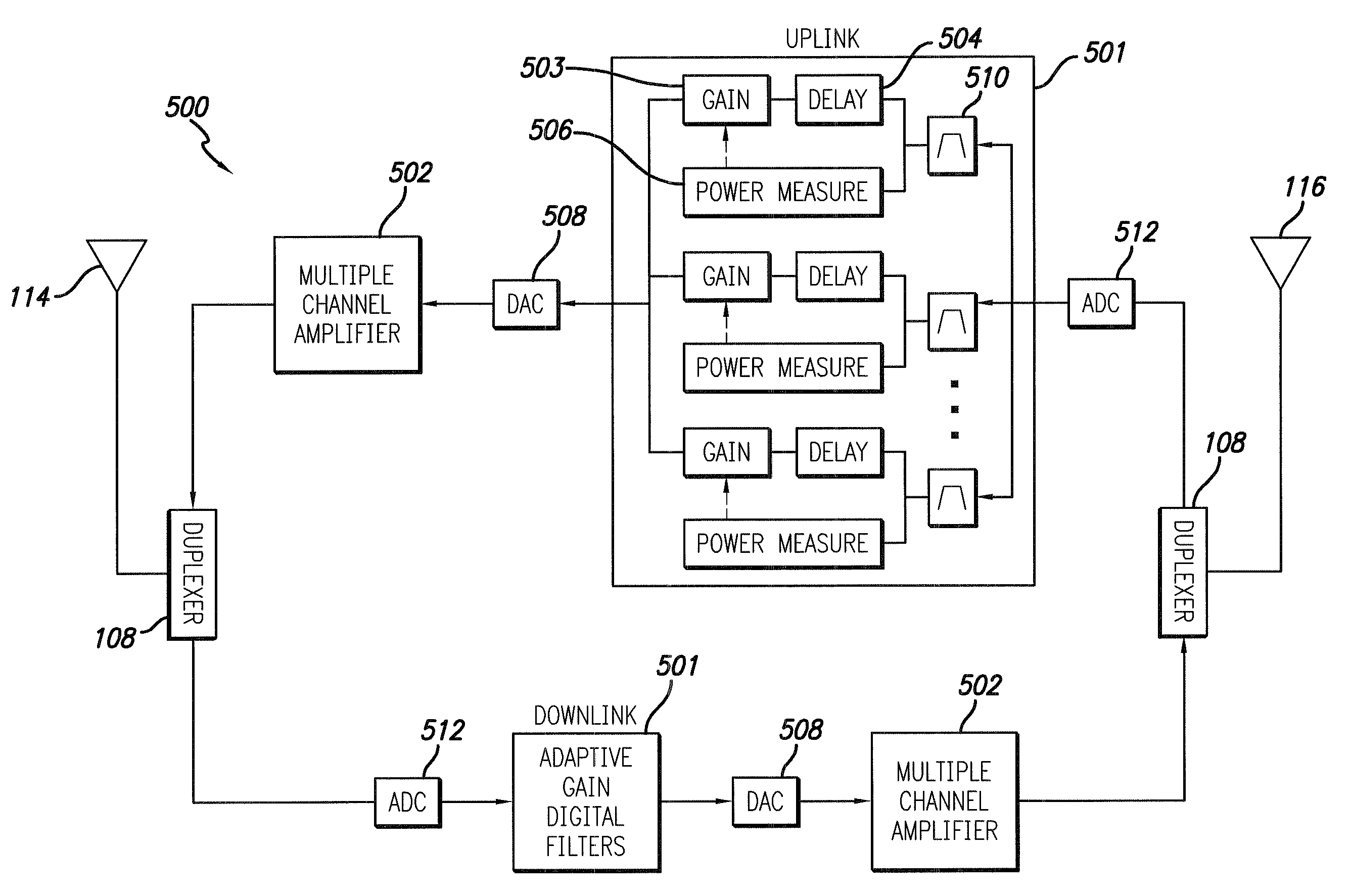
[0033]The present invention provides improved wireless over the air repeater and related communications systems and methods. A wireless over the air repeater receives signals, adds gain, and retransmits them. The incoming signals vary widely in amplitude according to the transmitter power and path loss. The outgoing, repeated signals require enough power to overcome path losses but not so much power as to overload the repeater's transmitter.

[0034]The input signals have a dynamic range that varies from weak and noisy to extremely strong. For global system for mobile communication (GSM) signals, the dynamic range can approach 70 dB because the weakest runs about −110 dBm and the strongest about −40 dBm. If the repeater had constant gain, the output would also require 70 dB of dynamic range. However, no reasonable power amplifier can provide enough power to add 70 dB to the maximum acceptable input. The minimum signal a repeater has to transmit depends on the path loss between its tran...


PUM


Abstract

An over the air repeater for enhancing wireless communication is provided. The repeater employs a system and method by which strong signals can be prevented from exceeding the repeater's uplink output limits while still providing full operational gain to any concurrently amplified weak signals, while adapting to time slot variations and optionally to frequency hopping variations. Power measurements are performed on each channel with resultant gain changes being performed on delayed versions of those same signals. Digital delay buffers are used to provide adequate processing time to make an accurate determination of the uplink signal levels of each RF carrier. The repeater alternatively monitors the downlink path from the donor base station to determine the frequencies to be processed on the uplink communication.

Description

RELATED APPLICATION INFORMATION[0001]The present application claims the benefit under 35 USC 119(e) of US provisional patent application Ser. No. 61 / 063,050 filed Jan. 31, 2008, the disclosure of which is incorporated herein by reference in its entirety.FIELD OF THE INVENTION[0002]The present invention relates to wireless communications systems and more specifically to systems and methods for providing RF coverage and / or call capacity so that users may connect to the wireless infrastructure.BACKGROUND OF THE INVENTION[0003]Traditional solutions for providing increased RF coverage and / or call capacity in wireless communications systems rely on some means of distributing RF energy. These range from high power, large coverage area towers to low power in-building pico-cells. There also exists a class of RF enhancement technologies known as RF repeaters. Some are bidirectional RF amplifiers that retransmit the signals received over the air from a host base station, known as over the air ...

Claims


Application Information

Patent Timeline
Patent Type & Authority Applications(United States)
IPC IPC(8): H04B7/14H04B17/40
CPCH04B7/15535H03G3/3047
Inventor SABAT, JOHNMILLAR, JEFFREY
Owner INTEL CORP
Why Eureka
Try Eureka