Impeller and cooling fan incorporating the same

Inactive Publication Date: 2009-08-06
FU ZHUN PRECISION IND SHENZHEN +1
View PDF9 Cites 11 Cited by
  • Summary
  • Abstract
  • Description
  • Claims
  • Application Information

AI Technical Summary

Benefits of technology

[0007]The present invention provides an impeller and a cooling fan incorporating the impeller. The cooling fan in accordance with an embodiment of the present invention includes a bottom housing, a top cover covering the bottom housing, a sidewall disposed between the bottom housing and the top cover, and an impeller enclosed in a space formed between the bottom housing, the top cover and the sidewall. The impeller includes

Problems solved by technology

If the heat is not timely removed, these electronic components may overheat.
However, increasing the revolving speed may corresp

Method used


Image

  • Impeller and cooling fan incorporating the same
  • Impeller and cooling fan incorporating the same
  • Impeller and cooling fan incorporating the same

Examples


Example

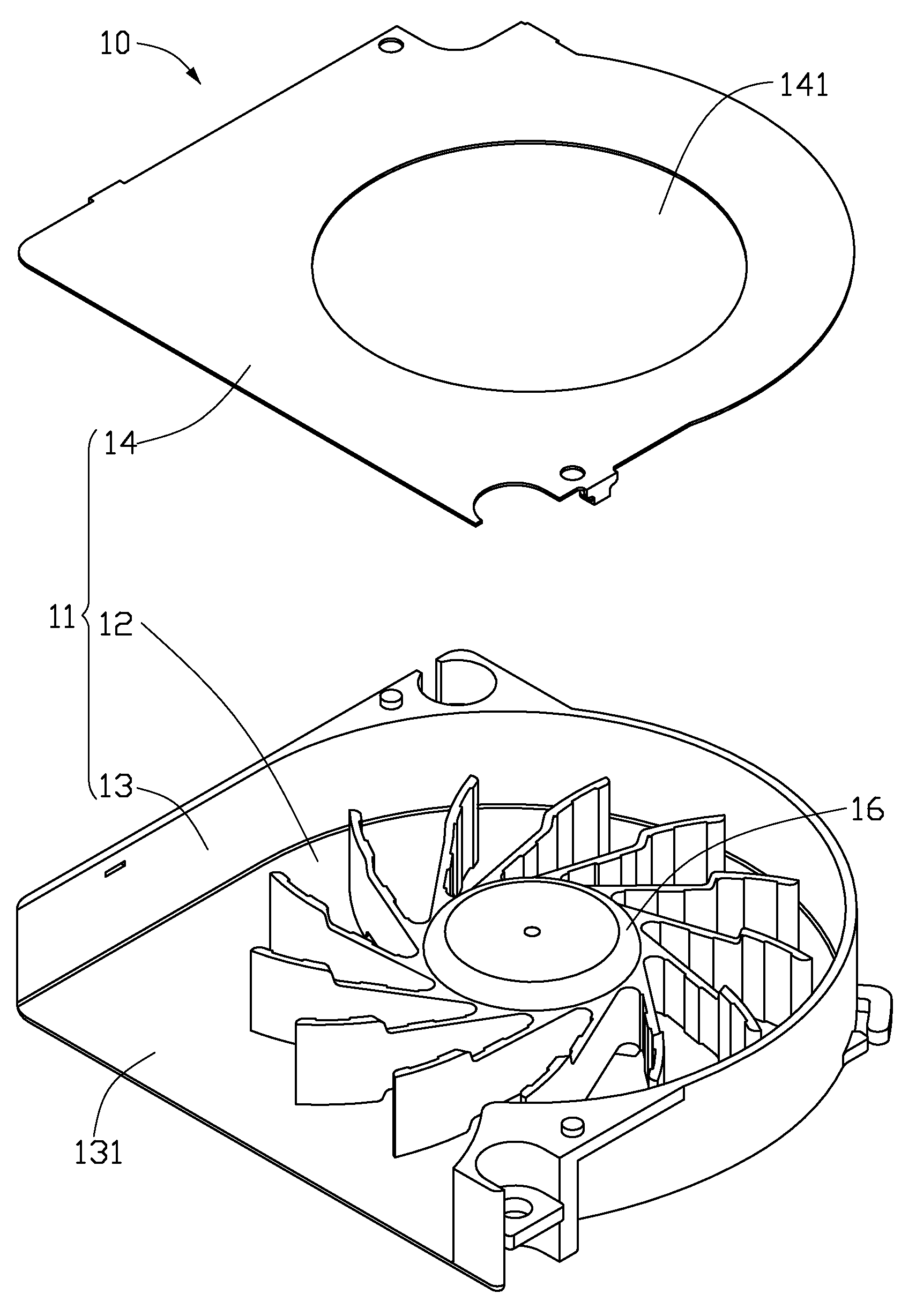
[0015]Referring to FIG. 1, a cooling fan 10 in accordance with a first embodiment of the present invention is shown. The cooling fan 10 includes an enclosure 11, a stator (not shown) and an impeller 16 received in the enclosure 11.

[0016]The enclosure 11 includes a bottom plate 12, a top cover 14 covering the bottom plate 12, and a sidewall 13 connected between the bottom plate 12 and the top cover 14. The sidewall 13 is integrally formed with the bottom plate 12 from a single piece. The impeller 16 is received in a space formed between the bottom plate 12, the top cover 14 and the sidewall 13. Two air inlets 141 are defined in middle portions of the top cover 14 and the bottom plate 12, respectively. In FIG. 1, only the air inlet 141 in the top cover 14 is shown. An air outlet 131 is defined in the sidewall 13 and perpendicular to the air inlets 141.

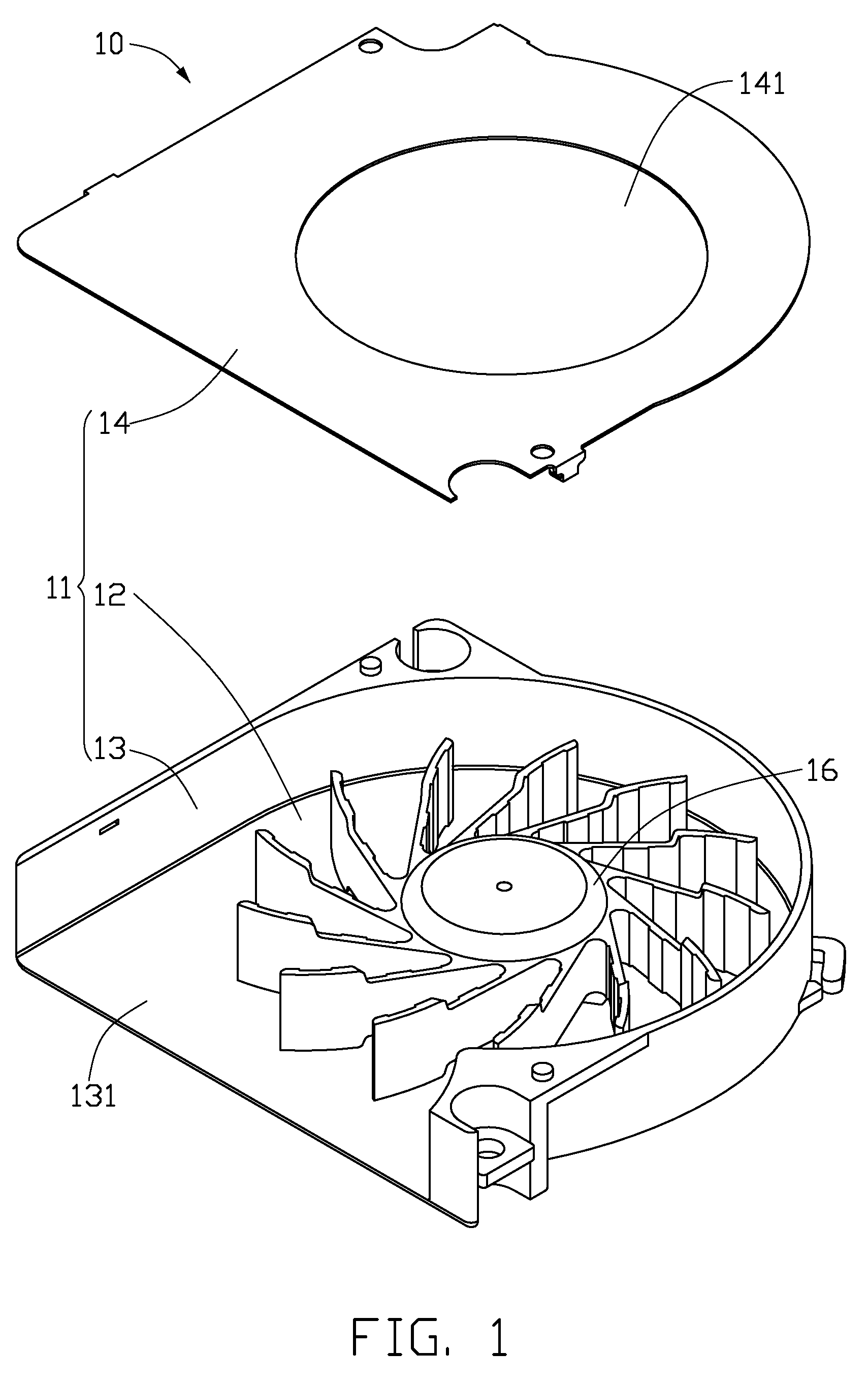
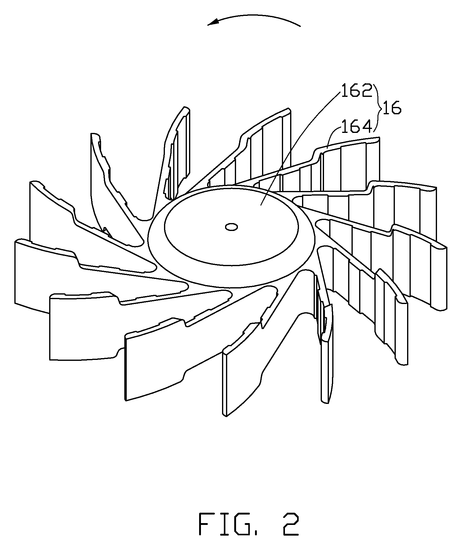
[0017]Referring to FIGS. 2 and 3, the impeller 16 includes a hub 162, and a plurality of blades 164 radially and outwardly extending fr...

Example

[0025]Referring to FIG. 6, a second embodiment of an impeller of the present cooling fan 10 is shown. The difference between the second embodiment and the first embodiment is: the blade 264 of the impeller of the second embodiment is a planar-type blade 264 whose windward and leeward surfaces 264a, 264b are straight linearly shaped as viewed from a top thereof. An extension direction A of a tip end of the windward surface 264a and an extension direction of a tip end of the leeward surface 264b each form a right angle with the tangent B of the rotation direction of the impeller. Alternatively, the blade 164 of the impeller 16 may be a forward-type blade. That is, windward and leeward surfaces of a rear blade both have tip ends slightly and forwardly bent toward a front blade. Extension directions of the windward and the leeward surfaces of the blade each form an acute angle with the tangent of the rotation direction of the impeller.

[0026]It is to be understood, however, that even tho...


PUM


Abstract

A cooling fan (10) includes a bottom plate (12) a top cover (14) covering the bottom plate, a sidewall (13) disposed between the bottom plate and the top cover, and an impeller (16) enclosed in a space formed between the bottom plate, the top cover and the sidewall. The impeller includes a hub (162), and a plurality of blades (164) radially and outwardly extending from the hub. Each of the blades includes a windward surface (164a) and a leeward surface (164b) opposite to the windward surface. The leeward surface of each blade defines three indents (171, 172, 173) therein. Two protrusions (174) are formed between adjacent indents. The uneven leeward surface is provided for lowering the noise level generated by the cooling fan during an operation thereof.

Description

BACKGROUND[0001]1. Technical Field[0002]The present invention relates to cooling fans, and more particularly to an impeller of a cooling fan which helps to decrease noise generated by the cooling fan when the cooling fan is operated.[0003]2. Description of Related Art[0004]It is well known that heat is produced by electronic components such as central processing units (CPUs) during their normal operations. If the heat is not timely removed, these electronic components may overheat. Therefore, heat sinks and cooling fans are often used to cool these electronic components.[0005]Generally, a cooling fan includes an enclosure, a stator received in the enclosure and an impeller being rotatable with respect to the stator. The impeller includes a hub and a plurality of blades radially and outwardly extending from the hub. When the cooling fan operates, the blades of the impeller rotate around the stator to drive an airflow to flow towards an electronic component, thus cooling the electroni...

Claims


Application Information

Patent Timeline
IPC IPC(8): F01D5/14
CPCF04D29/281F04D29/667F04D29/666F04D29/30
Inventor HWANG, CHING-BAIZHAO, ZHI-HUILIN, RAN
Owner FU ZHUN PRECISION IND SHENZHEN
Why Eureka
Try Eureka