
Lens apparatus and imaging apparatus including the same

Active Publication Date: 2013-10-31
CANON KK
View PDF3 Cites 3 Cited by
  • Summary
  • Abstract
  • Description
  • Claims
  • Application Information

AI Technical Summary

Benefits of technology

The present invention is about an imaging device that can reduce noise during shaking motion. This invention aims to provide an improved imaging device that can capture high-quality images without being affected by shaking or unwanted noise.

Problems solved by technology

Further, as a mechanism design for causing the focus lens to operate in an optical axis direction, it is difficult to eliminate a back-lash of a connection unit in view of operation guarantee and part accuracy under various temperatures.
As a result thereof, a mechanical collision noise cannot be prevented from being generated during the wobbling motion.
Therefore, in a case where the driving frequency is increased in order to improve controllability, the mechanical collision noise increases and thus such an inconvenience occurs that the noise tends to be recorded by a camera microphone as an operation noise of the focus lens.
Therefore, when capturing a moving image, recording of the mechanical collision noise generated during the wobbling motion is recognized as an unpleasant sound for a viewer of the moving image, resulting in inviting degradation of video quality (including sound).
Therefore, when capturing a moving image, recording of the mechanical collision noise during the wobbling motion and generation of the mechanical collision noise when capturing a still image or a moving mage are recognized as the unpleasant sound for the operator and a viewer of the moving image, resulting in inviting the degradation of the video quality (including sound).

Method used


Image

  • Lens apparatus and imaging apparatus including the same
  • Lens apparatus and imaging apparatus including the same
  • Lens apparatus and imaging apparatus including the same

Examples


Embodiment Construction

[0023]Various exemplary embodiments, features, and aspects of the invention will be described in detail below with reference to the drawings.

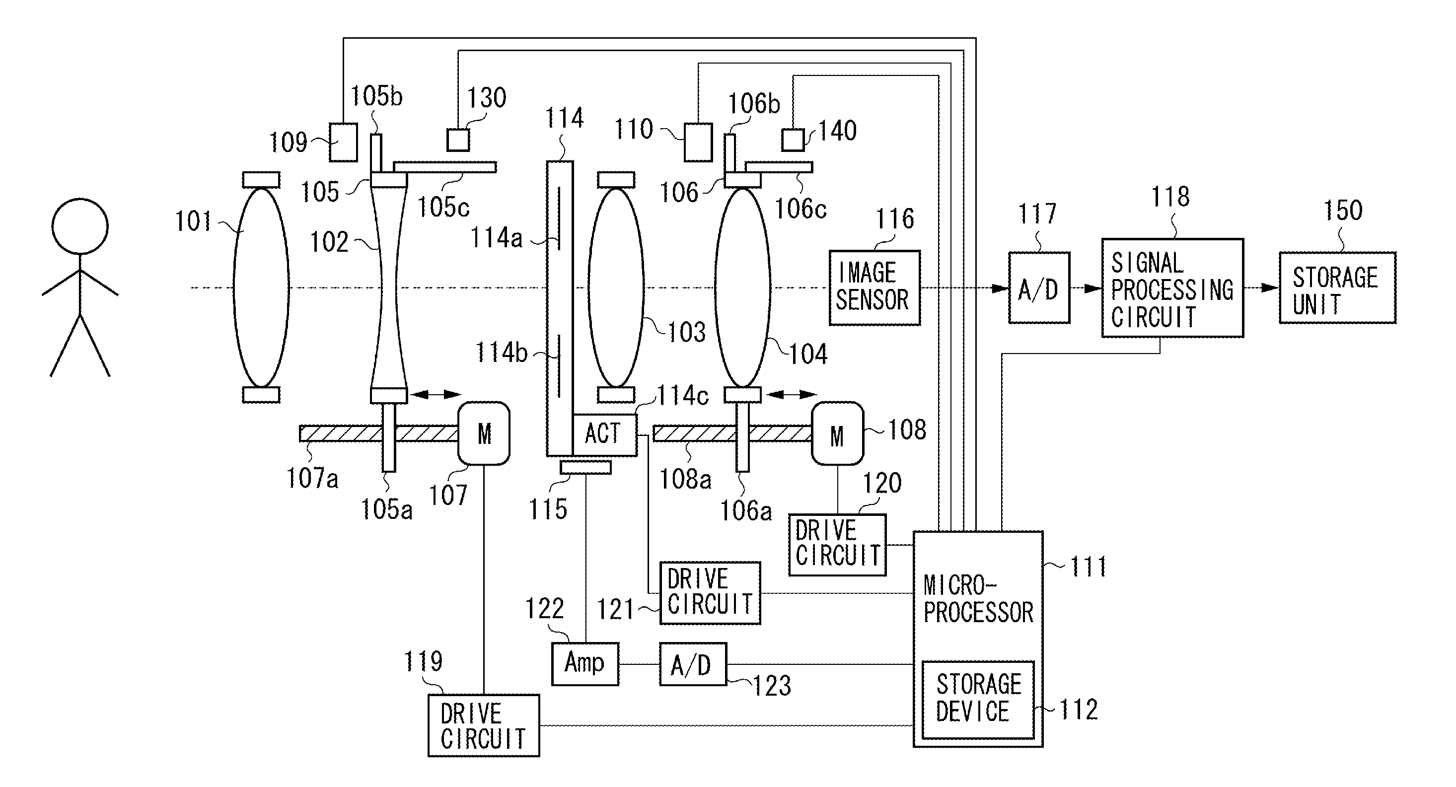
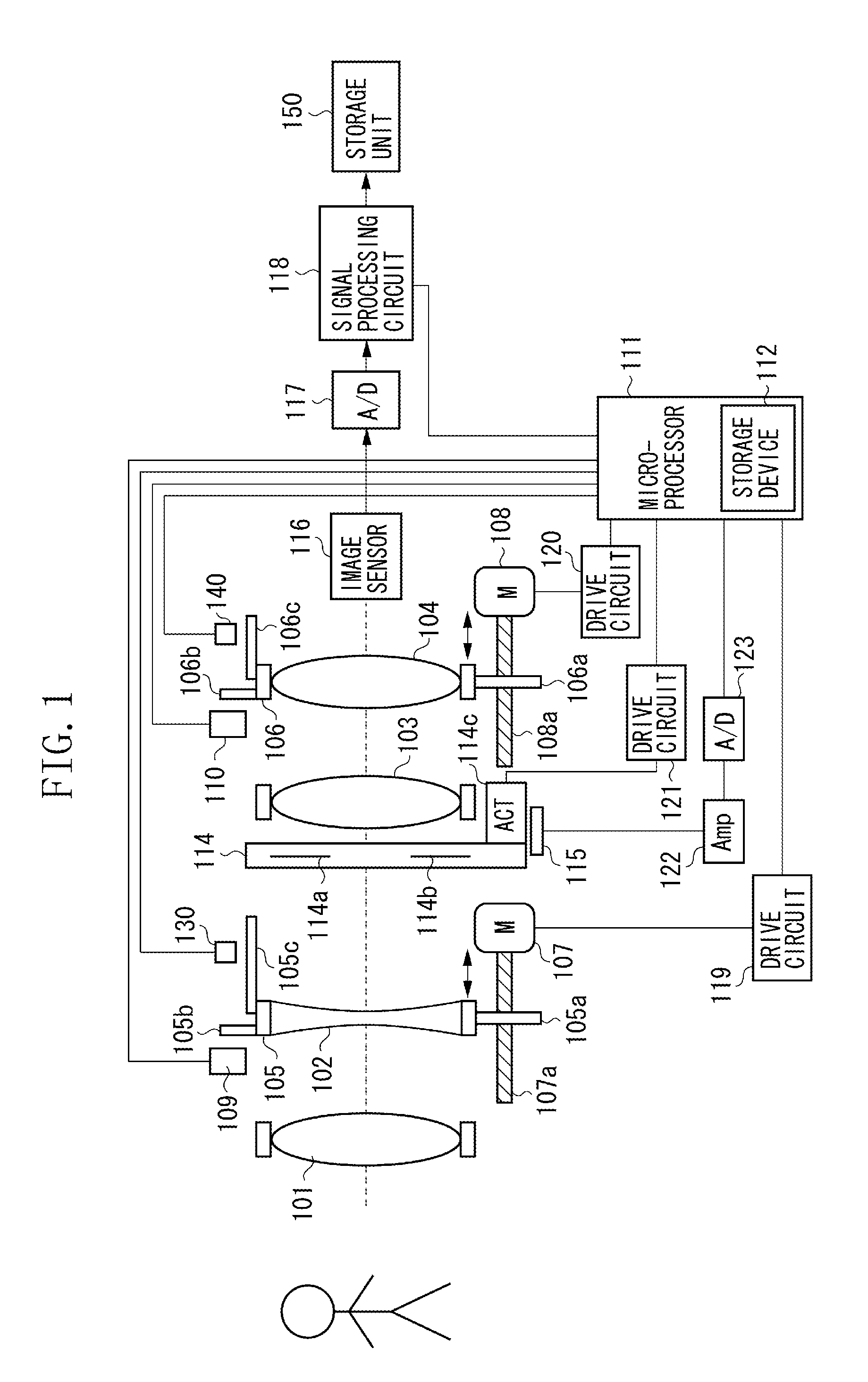
[0024]FIG. 1 is a block diagram illustrating an imaging apparatus (i.e., a lens apparatus and a camera apparatus) according to an exemplary embodiment of the present invention.

[0025]An imaging optical system of the lens apparatus includes, in an order from the object side, a field lens 101, a zoom lens group 102 as a variable power lens, a diaphragm (i.e., an aperture stop) 114 for adjusting the amount of light, an afocal lens 103, and a focus lens group 104 as a focusing lens.

[0026]An image sensor 116 as an image pickup unit includes a charge-coupled device (CCD) sensor or a complementary metal-oxide semiconductor (CMOS) sensor for photoelectrically converting an object image formed by the imaging optical system. The image sensor 116 is included in the camera apparatus. The lens apparatus can be connected to the camera apparatus including the ...


PUM


Abstract

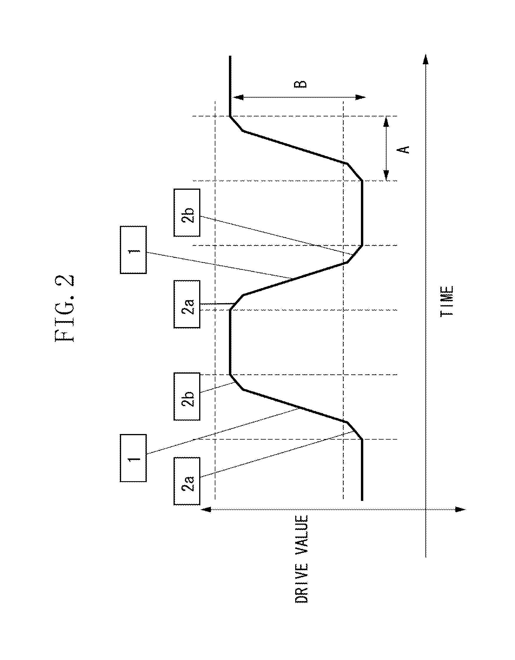
A lens apparatus includes an imaging optical system including a movable lens unit, a drive unit configured to drive the movable lens unit, and a control unit configured to cause the movable lens unit to perform a wobbling motion in an optical axis direction by alternatively outputting to the drive unit a first drive command for driving the movable lens unit at a first driving speed and a stop command for stopping driving of the movable lens unit, and to move the movable lens unit based on contrast information obtained from an image pickup unit during the wobbling motion of the movable lens unit, wherein, at least one of before and after outputting the first drive command to the drive unit, the control unit outputs to the drive unit a second drive command for driving the movable lens unit at a second driving speed lower than the first driving speed.

Description

BACKGROUND OF THE INVENTION[0001]1. Field of the Invention[0002]The present invention relates to a lens apparatus that performs a wobbling motion of a focus lens in order to determine a driving direction of the focus lens in which an object image comes closer to an in-focus state, and also relates to an imaging apparatus including the same.[0003]2. Description of the Related Art[0004]In a conventional still image capturing imaging apparatus or a conventional moving image capturing imaging apparatus, in order to determine a driving direction of a focus lens in which an object image formed by an imaging optical system comes to be in focus, the focus lens is minutely moved back and forth (i.e., a wobbling motion) in an optical axis direction of the imaging optical system.[0005]For example, as discussed in Japanese Patent Application Laid-Open No. 2010-63162, the wobbling motion of a focus lens is performed in a plurality of follow-up modes independent from a frequency of an exposure sy...

Claims


Application Information

Patent Timeline
IPC IPC(8): H04N5/232H04N5/225
CPCH04N5/23212H04N5/2254H04N23/55H04N23/673
Inventor ASANO, KOTA
Owner CANON KK
Learn More