System and method to combine a filter system with a freeze dryer to filter contamination of a vacuum pump

Active Publication Date: 2019-10-01
RHODES JR JESSE W
View PDF5 Cites 7 Cited by
  • Summary
  • Abstract
  • Description
  • Claims
  • Application Information

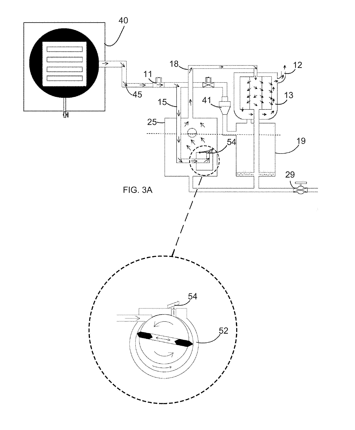
AI Technical Summary

Benefits of technology

This patent is about a system and method for using a filter to prevent contamination of a vacuum pump during the process of freeze drying. The system includes a vacuum pump connected to a freeze dryer through a vacuum hose, which removes pressure from the freeze dryer. An exhaust hose connects the vacuum pump to a coalescing filter, which collects water vapor and particulate gas and separates them from the oil in the oil composition. A control valve maintains oil pressure and a level of oil in the vacuum pump. A vent and exhaust hose inject clean air into the rejuvenated oil. A drain valve enables draining of impurities, and a final filter injects air into the oil exchanged between the sedimentary filter and the vacuum pump. The technical effect of this patent is to provide a system to prevent contamination of a vacuum pump during freeze drying by using a filter to collect water vapor and particulate gas, which can damage the oil in the vacuum pump.

Problems solved by technology

However, when they are used in the application of a freeze dryer, rust contaminates the system and thereby creates problems in the operation.
In order to keep the system operational after normal use, the system needs to be cleaned and re-lubricated with large amounts oil, which require hours to accomplish.
However, the pump's reservoir creates an extremely high amount of pressure.
The high pressure leads to problems and several mishaps have occurred, which include sight glasses blowing out and the covers of the reservoirs rupturing.
But these designs failed to adequately clean the oil and the internal parts of the pump.

Method used


Image

  • System and method to combine a filter system with a freeze dryer to filter contamination of a vacuum pump
  • System and method to combine a filter system with a freeze dryer to filter contamination of a vacuum pump
  • System and method to combine a filter system with a freeze dryer to filter contamination of a vacuum pump

Examples


Embodiment Construction

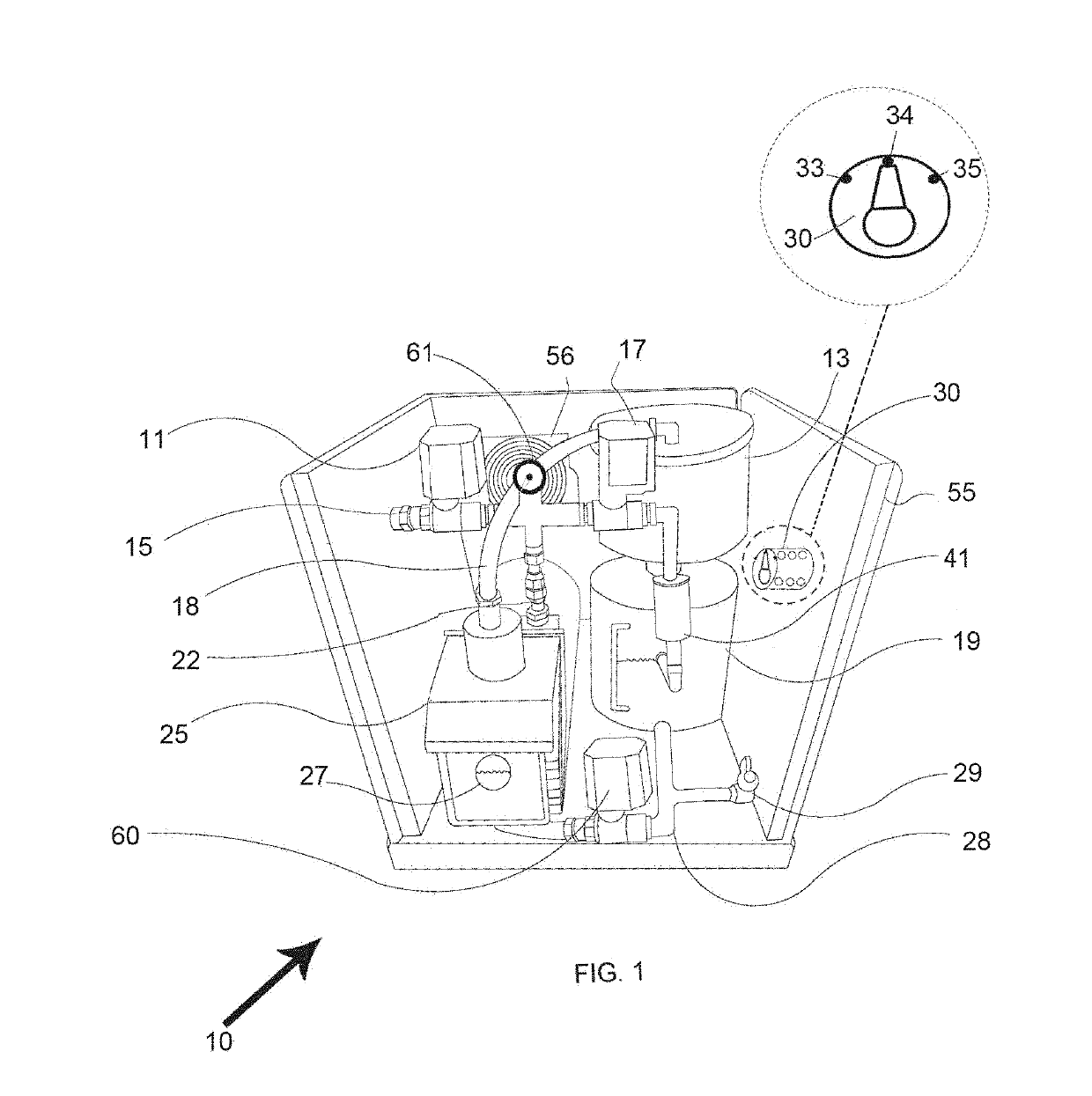
[0030]The following detailed description is merely exemplary in nature and is not intended to limit the described embodiments or the application and uses of the described embodiments. As used herein, the word “exemplary” or “illustrative” means “serving as an example, instance, or illustration.” Any implementation described herein as “exemplary” or “illustrative” is not necessarily to be construed as preferred or advantageous over other implementations. All of the implementations described below are exemplary implementations provided to enable persons skilled in the art to make or use the embodiments of the disclosure and are not intended to limit the scope of the disclosure, which is defined by the claims. For purposes of description herein, the terms “upper,”“lower,”“left,”“rear,”“right,”“front,”“vertical,”“horizontal,” and derivatives thereof shall relate to the invention as oriented in FIG. 1.

[0031]Furthermore, there is no intention to be bound by any expressed or implied theory...


PUM

PropertyMeasurementUnit
Lengthaaaaaaaaaa
Pressureaaaaaaaaaa
Timeaaaaaaaaaa

Abstract

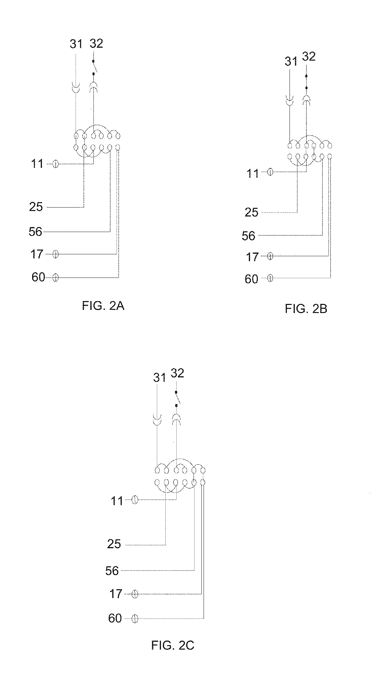
The present invention relates to a system and method for providing a filter to prevent contamination of vacuum pumps during use with freeze dryers. The system and method comprising of a vacuum pump connected to a freeze dryer, the vacuum pump evacuating pressure from the freeze dryer; the vacuum pump connected to a coalescing filter at least partially collects water vapor and the particulate gas, whereby the particulates in the particulate gas are at least partially separated from the gas, the coalescing filter further separating the oil from the water and particulates, whereby the oil is rejuvenated for use with the oil composition; an oil control valve to control pressure in the system and maintain a level of oil in the vacuum pump; a drain valve to enable draining of impurities, and a final filter that injects air into oil exchanged between the sedimentary filter and vacuum pump.

Description

FIELD OF THE INVENTION[0001]The present invention relates to a filtration system and method, and particularly to a filtration system and method that filters oil and contamination of vacuum pumps used with freeze dryers.BACKGROUND OF THE INVENTION[0002]Vacuum pumps can be used in a number of different operations. In some instances, vacuum pumps can be designed to be used on air conditioners and will still function even when containing ferrous metal parts. However, when they are used in the application of a freeze dryer, rust contaminates the system and thereby creates problems in the operation. For example, after use, the vacuum pump becomes full of rust water and particulate. In order to keep the system operational after normal use, the system needs to be cleaned and re-lubricated with large amounts oil, which require hours to accomplish.[0003]Previous attempts have tried to solve this problem in the past by using a vacuum pump's motor to move oil through a 7 micron car oil filter a...

Claims


Application Information

Patent Timeline
IPC IPC(8): F26B5/06B01D17/02A23L3/36B01D36/00B01D5/00B01D35/157B01D36/04B01D53/14B01D47/02B01D46/00B01D53/18
CPCB01D46/0019B01D46/0023F26B5/06B01D53/1425A23L3/363B01D5/006B01D47/021B01D17/02B01D35/1573B01D36/04B01D53/18B01D36/003A23V2002/00B01D2252/20B01D17/10B01D53/265A23L3/44B01D21/02B01D46/56B01D46/62
Inventor RHODES, JR., JESSE W.
Owner RHODES JR JESSE W
Why Eureka
Try Eureka