Vacuum cleaning tool having an air turbine with stabilizing air stream

Inactive Publication Date: 2007-07-24
DUPRO AG
View PDF6 Cites 2 Cited by
  • Summary
  • Abstract
  • Description
  • Claims
  • Application Information

AI Technical Summary

Benefits of technology

[0006]It is an object of the present invention to further develop a vacuum cleaning tool of the aforementioned

Problems solved by technology

The air cushion that is formed as a result of the flow conditions in the gap delimits the axial movements o

Method used


Image

  • Vacuum cleaning tool having an air turbine with stabilizing air stream
  • Vacuum cleaning tool having an air turbine with stabilizing air stream
  • Vacuum cleaning tool having an air turbine with stabilizing air stream

Examples


Example

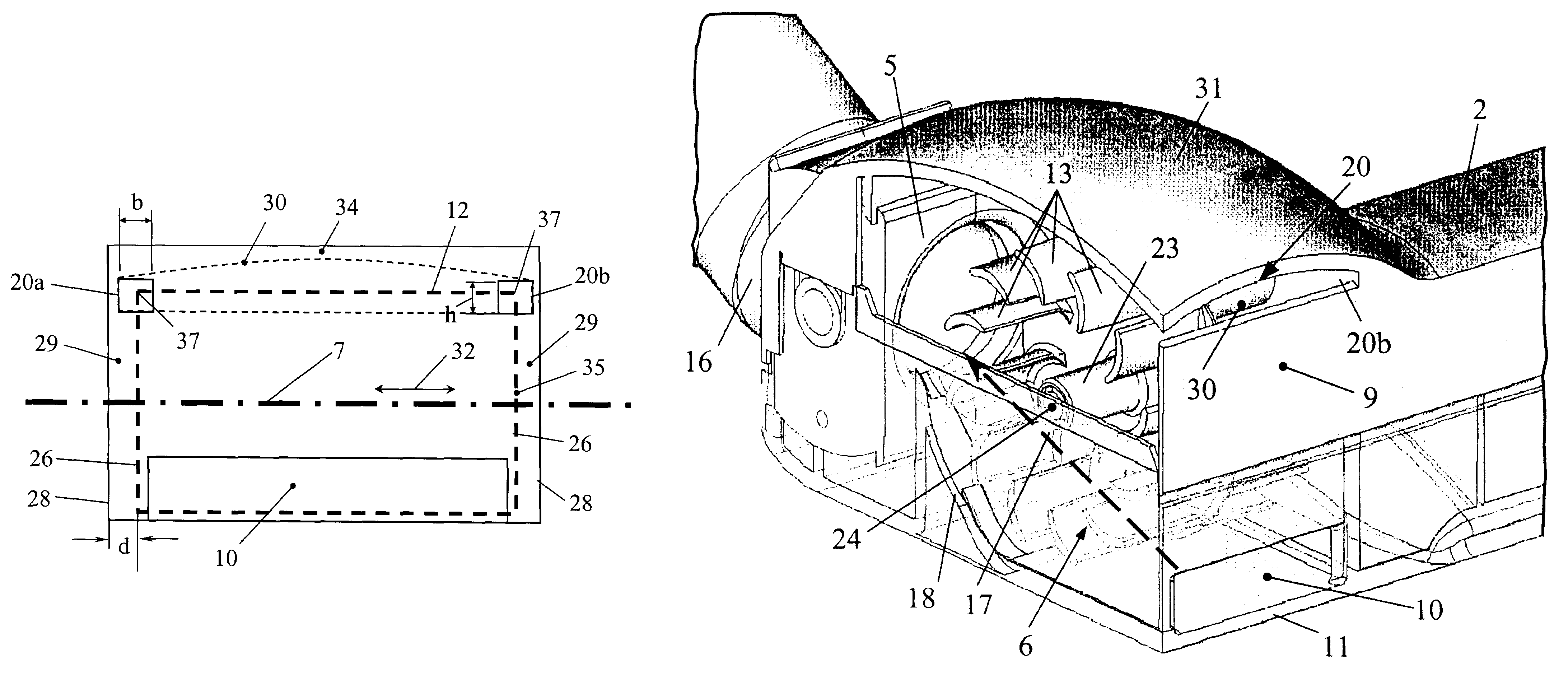
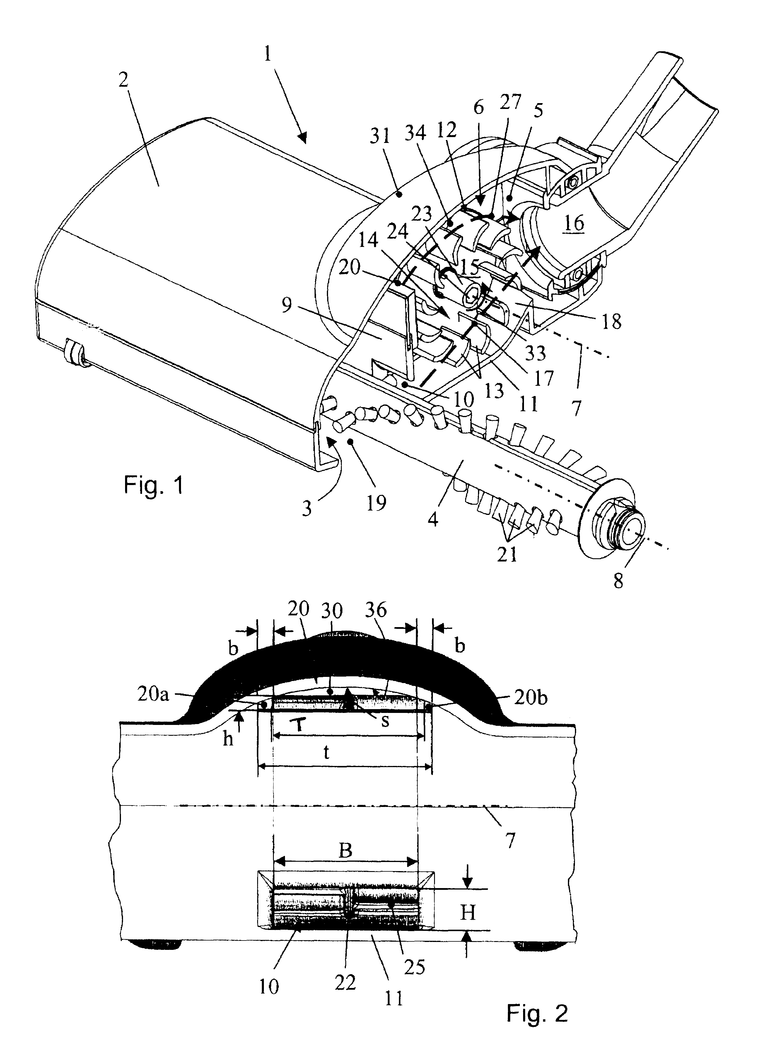
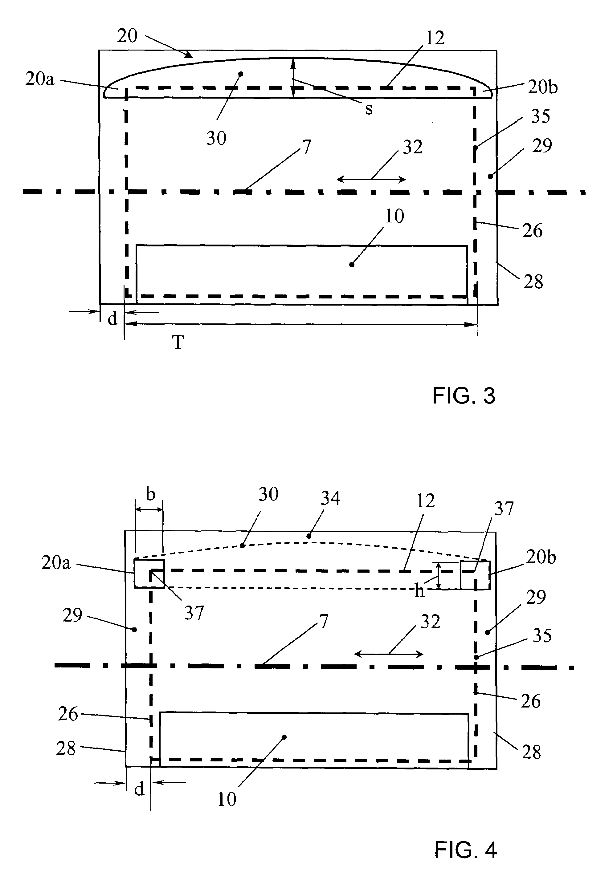
[0018]The vacuum cleaning tool 1 illustrated in FIG. 1 is comprised of a housing 2 that, in a plan view, has approximately the shape of a horizontally positioned T. The transverse beam of the T forms essentially the working chamber 3 in which a rotatingly driven working tool 3 in the form of a brush roller is rotatably supported. In the longitudinal beam of the T, a turbine chamber 5 is formed that is arranged approximately centrally relative to the working chamber 3. In the turbine chamber, an air turbine 6 is arranged whose rotational axis 7 is essentially parallel to the axis of rotation 8 of the working tool 4. The partition 9 arranged between the turbine chamber 5 and the working chamber 3 has a first intake window 10 for a driving suction air stream 17 and a second intake window 20 for a partial suction air stream 27, wherein the two windows 10, 20 are arranged on opposite sides relative to a plane extending through the rotational axis 7. The first intake window 10 is arranged...


PUM


Abstract

A vacuum cleaning tool has a housing having a turbine chamber and a bottom plate. A working tool is rotatably supported in the housing. An air turbine for driving the working tool is arranged in the turbine chamber and has axial end faces defining a gap relative to the chamber sidewalls. A turbine chamber wall has a first intake window and at least one second intake window. The first intake window supplies a driving suction air stream to the peripheral turbine surface on a first side of a plane that extends through the turbine axis. The second intake window supplies a partial suction air stream to the turbine chamber that enters the turbine chamber on a second side of the plane extending through the turbine axis. The second intake window overlaps at least partially at least one gap and the partial suction air stream flows into the gap.

Description

BACKGROUND OF INVENTION[0001]1. Field of the Invention[0002]The invention relates to a vacuum cleaning tool, in particular, for a vacuum cleaning device such as a vacuum cleaner or the like. The vacuum cleaning tool comprises a rotatingly driven working tool and has a housing with a bottom plate and a working slot formed in the bottom plate. The working tool that is rotatably supported in the housing acts through the working slot onto the surface to be cleaned on. The vacuum cleaning tool comprises an air turbine arranged in a turbine chamber of the housing and has axial end faces forming together with the sidewalls of the turbine chamber a gap, respectively. The turbine drives the working tool by means of a drive connection. In one turbine chamber wall of the turbine chamber, a first intake window for a driving suction air stream and a second intake window for a partial suction air stream are provided, wherein the driving suction air stream is supplied on one side of the rotational...

Claims


Application Information

Patent Timeline
IPC IPC(8): A47L9/04A47L9/00
CPCA47L9/0081A47L9/0416
Inventor WORWAG, PETER
Owner DUPRO AG
Why Eureka
Try Eureka