System and inlet device for separating a mixture

Active Publication Date: 2009-08-06
FMC TECH CV
18 Cites 24 Cited by

AI-Extracted Technical Summary

Problems solved by technology

In applications where the available static head of liquid is too short, these kind of cyclonic inlet devices could not be used.
This is because, if gas breaks through at the bottom of the cyclone, there is a possibility that large amounts of liquid are lifted upwards as the gas enters the liquid surrounding the cyclone.
This liquid may in turn overload any second stage separation unit installed downstream of the inlet cyclone.
If an inlet cyclone were to be installed that is not (partially) submerged in the liquid in the lower compartment, then the following problems may arise.
In some circumstances, too much gas escapes out of the ...

Method used

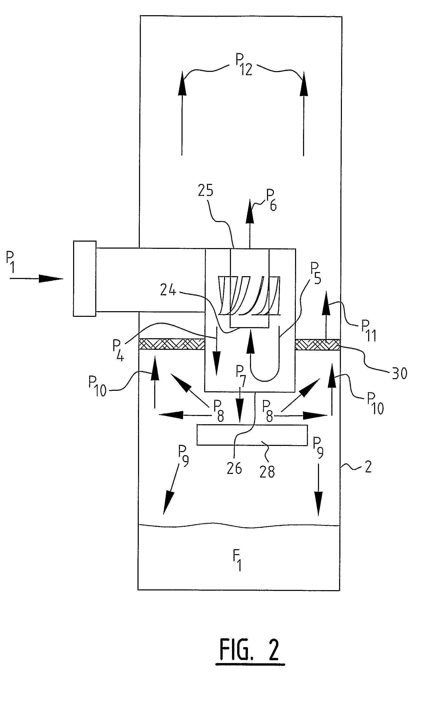
[0052]The gas/liquid mixture leaving the bottom of the cyclone 7 together with the liquid impinges (P7) upon the plate-like momentum breaker 28 causing the mixture to diverge sideways (P8). See FIG. 2. A part of the diverged mixture (P9) will end up in the fluid F1 accumulated at the bottom of the vessel 2, while the remaining part of the mixture will be forced upward (P10). The wire mesh pad 27 on top of the momentum breaker plate 28 will partially absorb the momentum of the mixture at the same time as it will drain some liquid out of the gas/liquid mixture. Liquid is typically seen draining downward through the lower part of the wire mesh pad 27. The absorption of the liquid improves the separation efficiency of the separator. Moreover, the gas that leaves the momentum breaker 28 becomes more efficiently distributed. Dependent on gas load, separation within the momentum breaker 28 may also actually be seen since coalescence of liquid droplets takes place within the demister element. Since the gas/liquid leaves the momentum breaker 28 at much lower vel...

Benefits of technology

[0038]Especially good results, however, may be obtainable in a further embodiment wherein the separation means comprise one or more third demister elements (second stage), for example, one or more agglomerators/coalescers, for instance in an upright vessel extending substantially horizontally over substan...

Abstract

The invention relates to a system for separating a mixture of gas and liquid into a heavy fraction and a light fraction, the system comprising: —a separation vessel having a vessel inlet for the supply of the mixture to be separated, an upper vessel outlet for the discharge of the light fraction and a lower vessel outlet for the discharge of the heavy fraction; —at least one inlet device for pretreatment of the incoming mixture, the inlet device, comprising a casing having a liquid outlet for the discharge of a first mixture part mainly containing liquid to a lower compartment of the separation vessel; and at least one demister element arranged at a position below the liquid outlet for separating liquid from the gas in the first mixture part flowing from the liquid output.

Application Domain

Technology Topic

Image

  • System and inlet device for separating a mixture
  • System and inlet device for separating a mixture
  • System and inlet device for separating a mixture

Examples

  • Experimental program(1)

Example

[0057]In FIG. 4, a third embodiment of the present invention is shown. In this embodiment, both a wire mesh pad 27 above the momentum breaker plate 28 and a wire mesh pad 30 have been arranged in the vessel 2.
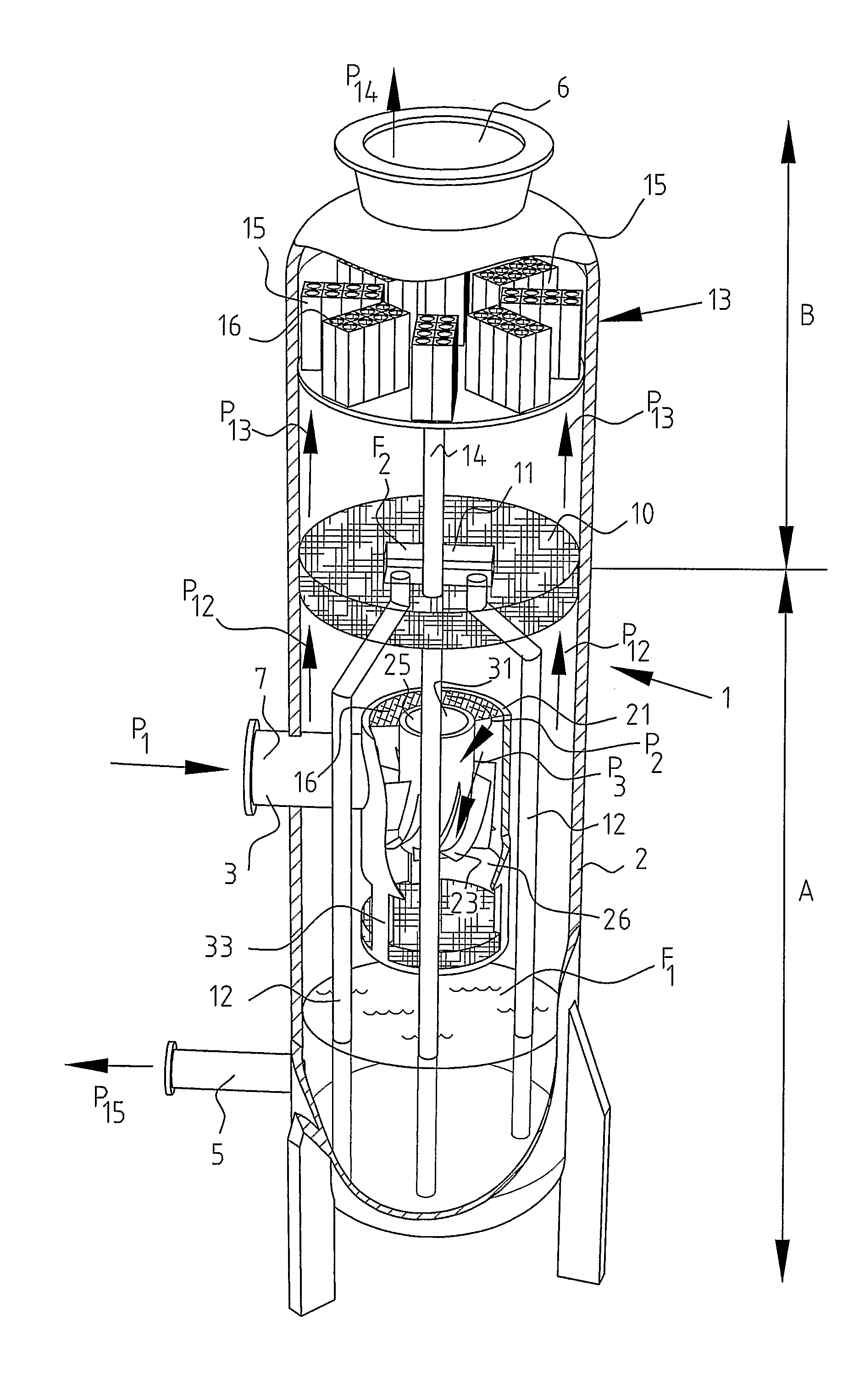
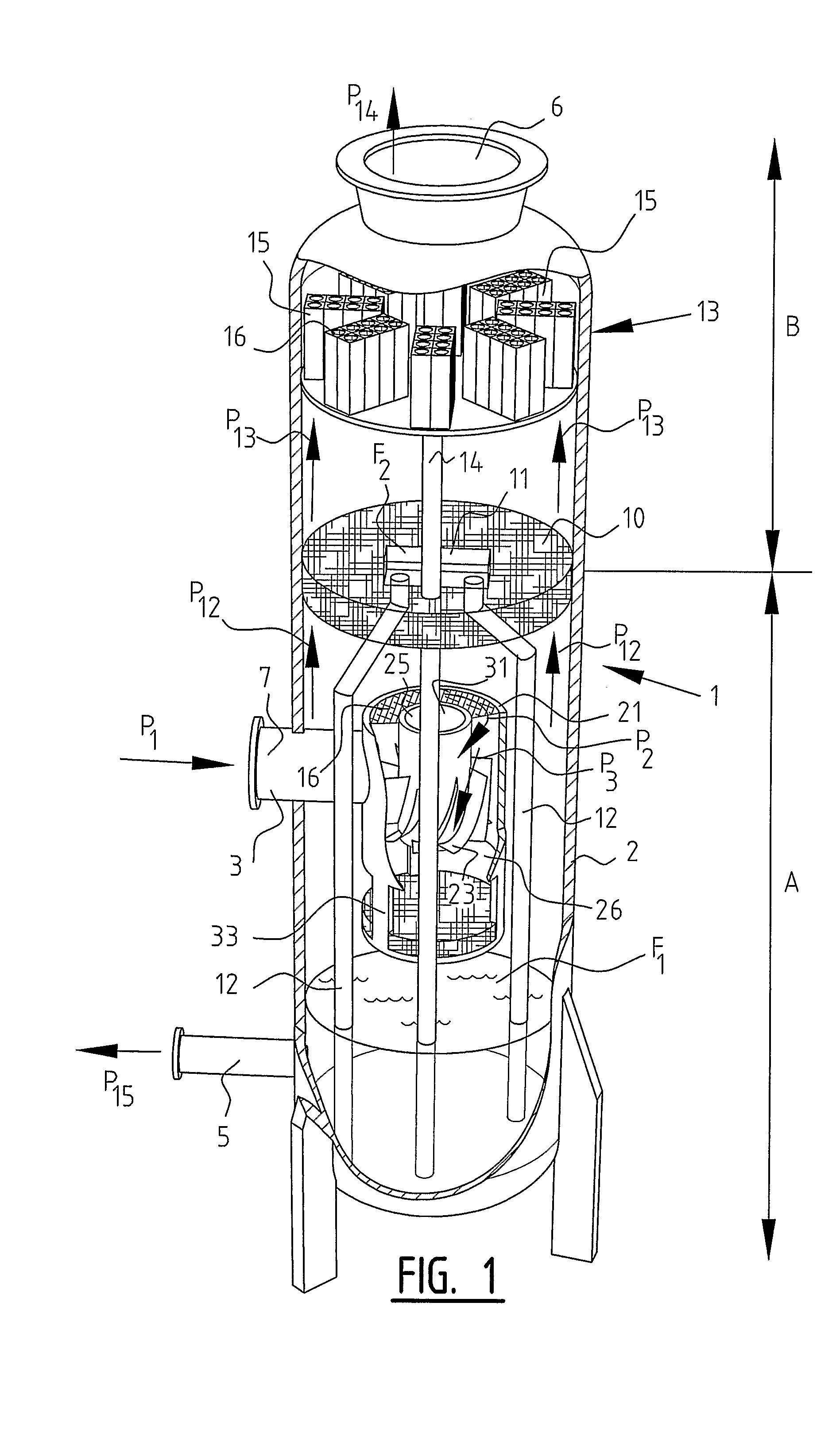
[0058]In FIG. 1, an example is shown of further separation stages for separating the liquid from the gas/liquid mixture or light fraction after the mixtures from the gas outlet 25 and the liquid outlet 26 have been reunited. The separated light fraction, although it contains less liquid than the mixture supplied from outside, still has a certain liquid content, is first guided (P12) at high speed through an agglomerating element 10 (also known as a demister element or a coalescer) in the second stage of the separation process. The agglomerating element 10 is disposed horizontally in the vessel 2 and thereby forms a separation between lower compartment A and upper compartment B of vessel 1. A detailed description of an example of a suitable agglomerating element 10 is given in WO 03/074156 A1, which is hereby incorporated in its entirety by reference.
[0059]The agglomerating element 10 causes agglomeration of the liquid, i.e., collecting or accumulating of the liquid in relatively large liquid droplets. The agglomerating element 10 may be embodied in a mesh, for instance, in the form of a number of layers of metal gauze. Other types of agglomerating units may, however, also be applied, such as one or more layers of structured packing or of vanes or vane packs. The coalescer is designed to function in a flooded condition. In order to prevent too much liquid collecting above the agglomerating unit surface and the distribution of the liquid displacing to the further separator still being adversely affected, the liquid is discharged via a collecting trough or collecting reservoir 11 in which liquid F2 can be collected. Via two discharge conduits 12 extending below the level of liquid F1 at the bottom of the lower compartment, the collected liquid F2 can be carried to the lower compartment A of vessel 2, where the liquid can be drained via the discharge stub 5.
[0060]The mixture which is displaced further upward (arrow P13), in which mixture a relatively large amount of gas and liquid is present in relatively large droplets, is further separated in a third stage by a number of cyclone separators. A number of boxes 13 is arranged for this purpose in upper compartment B of vessel 2 (FIG. 1). Provided downstream thereof is the connecting stub 6 for discharging the gas (P14) which is dried to a considerable extent. Boxes 13 are each separately or jointly provided with a downcomer 14 which is in communication with liquid F1 at the bottom of the vessel for draining liquid from each of the boxes.
[0061]In one embodiment, eight cyclones 15 are arranged in each of the boxes 13. In a particularly effective embodiment, these are axial recycle cyclones, preferably of the type as described in WO 00/25931, the disclosure of which is herein incorporated in its entirety by reference. Each cyclone 15 comprises, in this embodiment, a cylindrical wall 15 which forms on the underside an inlet for the gas/liquid mixture and has an outflow opening 16 on the upper side thereof. Roughly centrally in the space enclosed by the cylindrical wall is placed a so-called swirl element which is provided with blades for setting the mixture into rotating movement. A part of the mixture is flung outward by this rotating movement and transported via an interspace to a recycle conduit. The recycle conduit extends through the swirl element. Further connected to the space between the wall and the wall of the box is a downcomer 6, which is connected on the other side to the space at the bottom of the vessel for collecting liquid F1. The separation efficiency of the type of axial recycle cyclone, in combination with the inlet device as described herein and even more so in combination with the agglomerating element 10 described herein, has been found to be particularly high, which enables, among other things, a compact embodiment of the installation.
[0062]The above-described three stage upright separation vessel provides an efficient separator for separating liquid/gas mixtures, for example, oil/gas mixtures, extending in an upright position. Although the upright separator is very compact and may be used in many applications, the separation vessel may also be placed in a lying or horizontal position. FIG. 5 shows a further embodiment wherein the inlet cyclone, which may be identical to the inlet cyclone described above or operates similarly, is mounted in a horizontal separation vessel or gravitation vessel 2′. In order to demist the gas/liquid leaving the liquid outlet opening 26, a wire mesh pad 35 is attached to the casing 21 and the momentum breaker plate 28 such that a closed area is formed through which the mixture from the lower output of the inlet device must flow. A part of the liquid present in the gas/liquid mixture traversing the wire mesh pad 35 agglomerates therein. The liquid then falls back into the liquid sump F1 at the bottom of the vessel 2′ and is discharged through a liquid outlet (not shown in the figure) in the vessel 2′. The remaining gas/liquid is fed, together with the gas/liquid mixture from the gas outlet opening 25, to one or more further stages (if any) for additional separation of liquid and gas.
[0063]Although the above embodiment, wherein a mesh surrounding the liquid outlet of the inlet cyclone is used, is described in connection with a lying vessel, such mesh surrounding the liquid outlet may, in a different preferred embodiment, also be used in an upright separation vessel.
[0064]In the embodiments described herein, the separation vessel is provided with one inlet device. In other embodiments, two or more inlet devices (cyclones) are arranged inside the vessel. When, for example, the height from the inlet to the liquid surface is too short to fit the inlet cyclone, two or more smaller-sized inlet devices are used. Each inlet cyclone can have its own momentum breaker plate and/or mesh or all inlet cyclones may share one common momentum breaker and/or mesh pad.
[0065]In the embodiments shown in the drawing, the rotation means of the inlet cyclone comprise one or more guiding vanes. The guiding vanes impart a rotating movement on the mixture flowing along the guiding vanes. In other embodiments, however, the inlet device comprises other rotation means, e.g., a tangential inlet part, for instance formed by an inner wall part of the casing, the inner wall part being curved so as to bring the mixture flowing there along into rotating movement. The tangential inlet causes the mixture entered in the inlet device to rotate.
[0066]The particular embodiments disclosed above are illustrative only, as the invention may be modified and practiced in different but equivalent manners apparent to those skilled in the art having the benefit of the teachings herein. For example, the process steps set forth above may be performed in a different order. Furthermore, no limitations are intended to the details of construction or design herein shown, other than as described in the claims below. It is therefore evident that the particular embodiments disclosed above may be altered or modified and all such variations are considered within the scope and spirit of the invention. Accordingly, the protection sought herein is as set forth in the claims below.

PUM

PropertyMeasurementUnit
Momentum
Interface
tensileMPa
Particle sizePa
strength10

Description & Claims & Application Information

We can also present the details of the Description, Claims and Application information to help users get a comprehensive understanding of the technical details of the patent, such as background art, summary of invention, brief description of drawings, description of embodiments, and other original content. On the other hand, users can also determine the specific scope of protection of the technology through the list of claims; as well as understand the changes in the life cycle of the technology with the presentation of the patent timeline. Login to view more.

Similar technology patents

Method and device for selecting hyperspectral image band based on key band extraction

ActiveCN106778680AImprove Band Selection EfficiencyGood resultCharacter and pattern recognitionBand selectionSpectral image
Owner:HANGZHOU DIANZI UNIV

Classification and recommendation of technical efficacy words

Why Eureka
Try Eureka