

Wound coil compression connector
- Summary
- Abstract
- Description
- Claims
- Application Information
AI Technical Summary
Benefits of technology
Problems solved by technology
Method used
Image

Examples
example
[0084]A prototype connector was built of a multi-contact electrical connector and the resistance of the connector was tested. As described above, both the passage of time and thermal cycling may increase resistance in a connector. The resistance of a conductor may also be a function of the temperature of the connector. Accordingly, voltage drops across different portions of the connector were measured to determine an initial resistance of different portions of the connector. Then measurements of voltage drop across all of the connector were taken at different temperatures after various numbers of thermal cycles had been completed to show the resistance across the connector as a function of temperature and number of thermal cycles.
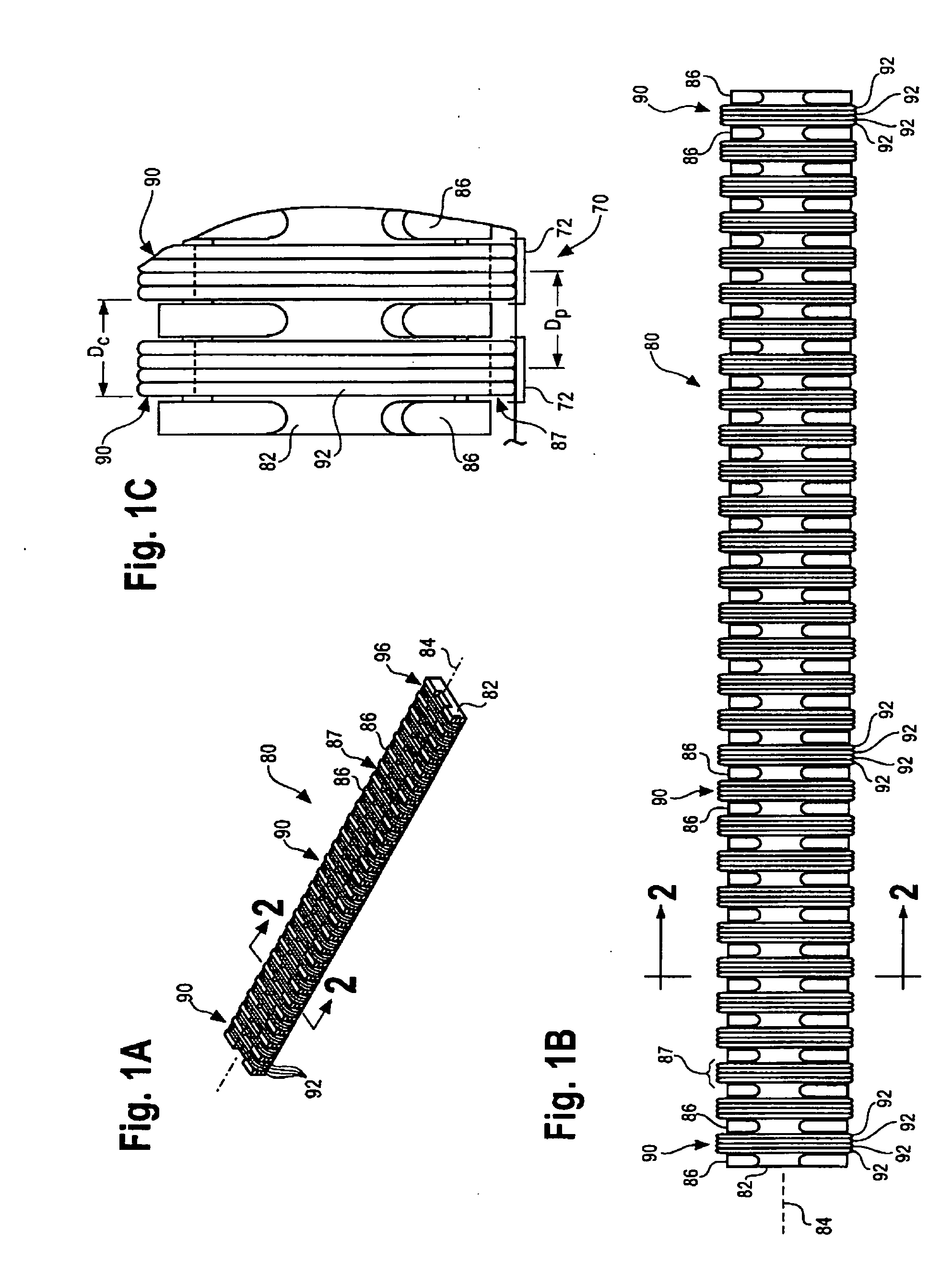
[0085]The prototype connector included two connector elements, each with 10 bays and 4 loops of wire that formed a coil in each bay. The bays were spaced such that 0.05 inches separated a point on a first bay and a corresponding point on an adjacent bay (i....
PUM
 Abstract
Description
Claims
Application Information