

Linear or disk brush material, cylindrical brush, and method of manufacturing the linear or disk brush material
a technology of linear or disk brush and cylindrical brush, which is applied in the direction of brushes, manufacturing tools, metal working apparatuses, etc., can solve the problems of easy folding damage, unsuitable rotary brushes for heavy cleaning work, and loosened brushes, so as to achieve easy adjustment of density, easy change of brush density, and high degree of freedom
- Summary
- Abstract
- Description
- Claims
- Application Information
AI Technical Summary
Benefits of technology
Problems solved by technology
Method used
Image

Examples
embodiment 1
[0098]An embodiment of the present invention will be described with reference to FIGS. 1A, 1B, and 2A to 2C.
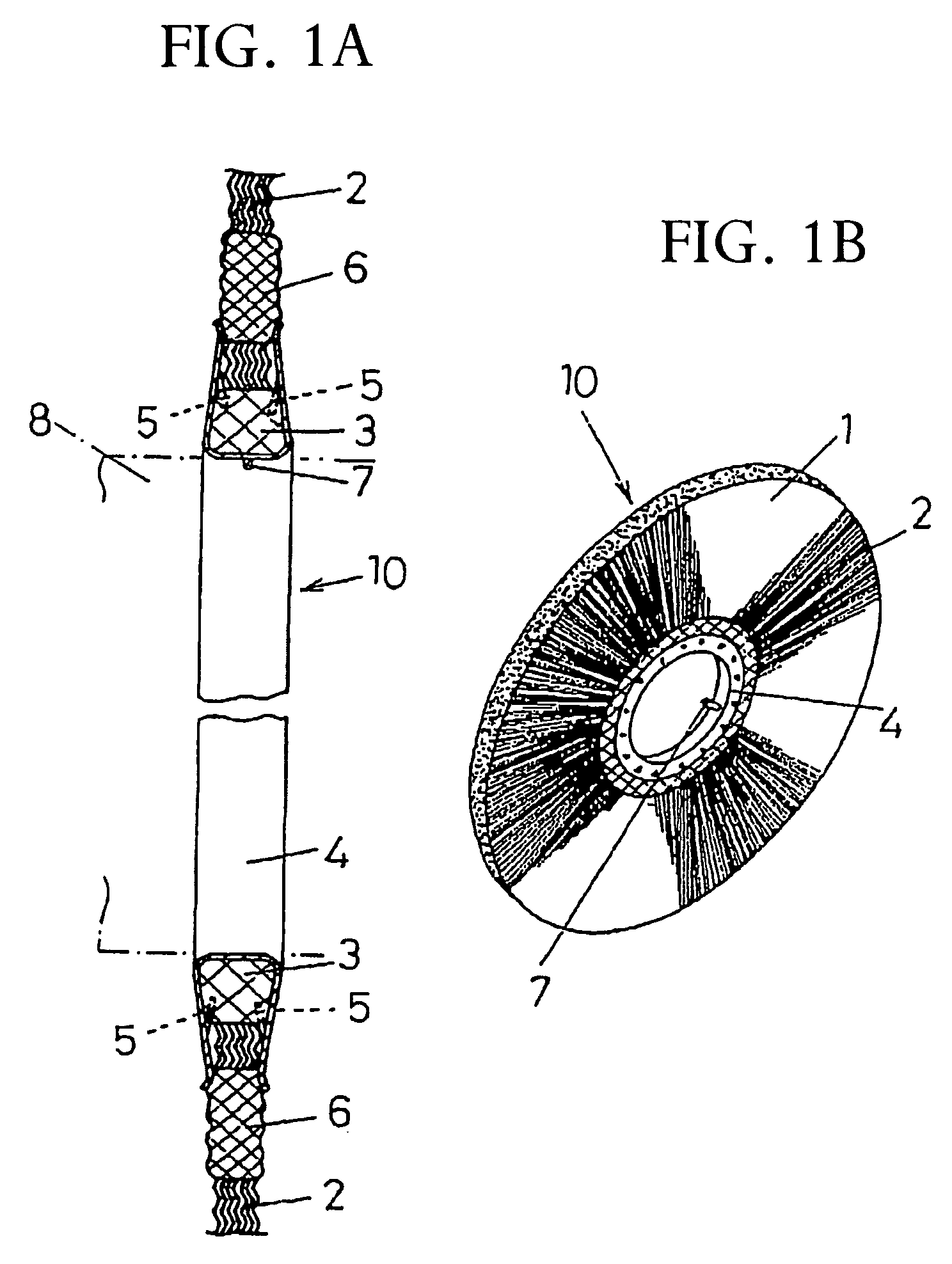
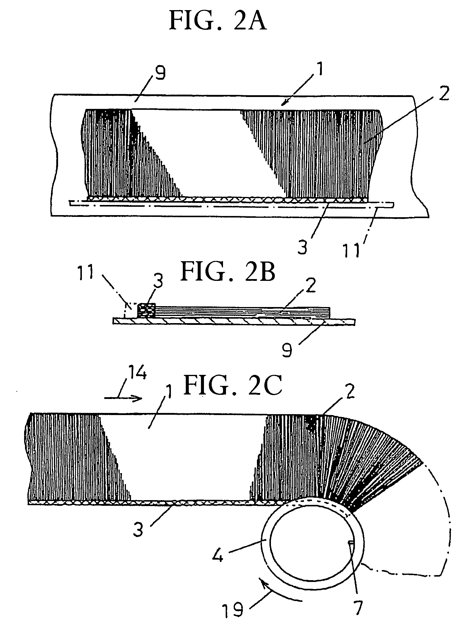
[0099]A large number of steel brush wires 2 and 2 molded in wavy shape are linearly arranged to a predetermined thickness (FIG. 2A). Polypropylene is applied to and penetrated into the root portion side of the steel brush wires 2 and 2. The root portion side of the steel brush wires 2 and 2 are cooled and solidified to obtain a solid portion 3. A steel brush band 1 is thus formed (FIG. 2A).
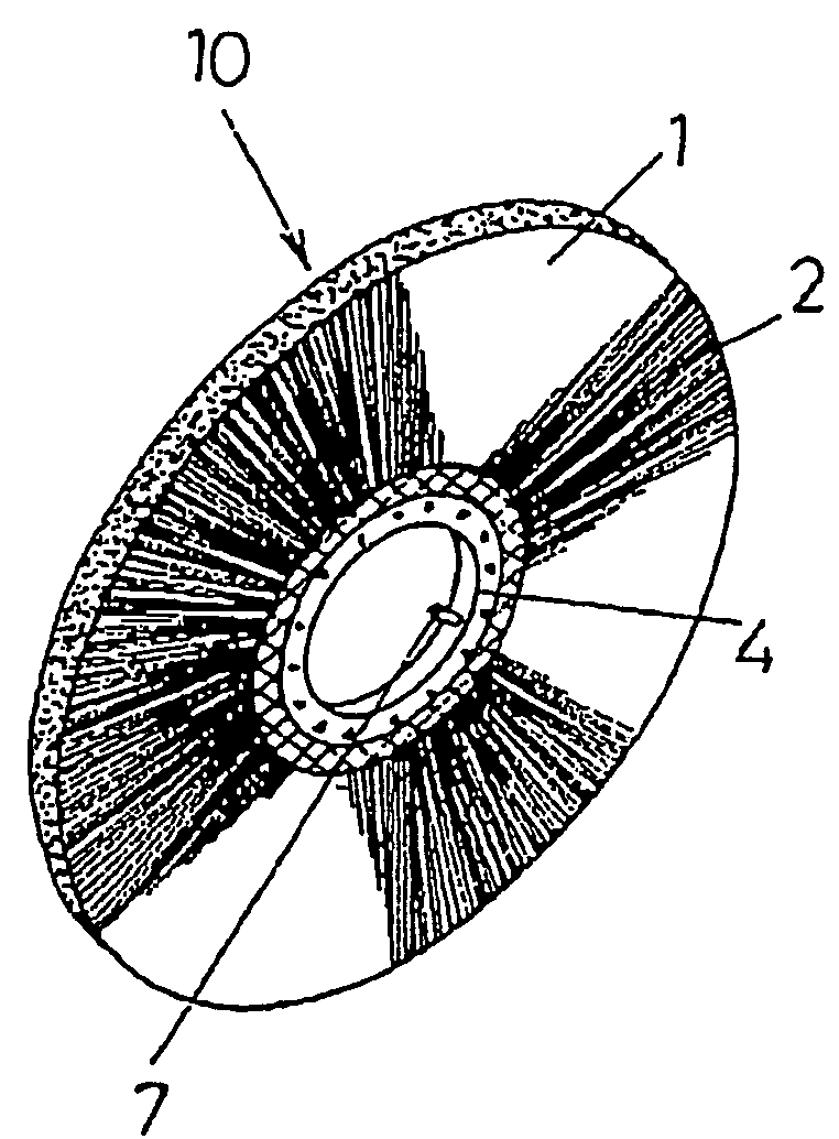
[0100]The solid portion 3 of the steel brush band 1 is fitted into the outer peripheral portion (U-shaped portion) of a ring-like steel channel 4 which is separately manufactured and has a U-shaped cross section. The side wall of the steel channel 4 is pressed to form a latching section 5 inwardly of the steel channel 4. The edge of the latching section 5 is pressed and latched to the solid portion 3 of the steel brush band 1 (FIG. 1A).
embodiment 2
[0107]A method of manufacturing the disk steel brush material 10 according to the present invention illustrated in FIG. 1B will be described with reference to FIGS. 1A, 1B, and 2A to 2C.
[0108]The steel brush wires 2 cut to a predetermined length are stacked on a base plate 9 (or conveyer) to a predetermined thickness. The ends of the steel brush wires 2 are arranged by the base plate 9 and a guide plate 11 to make the thickness fixed.
[0109]Propylene resin is extruded and applied to the root portion side of the steel brush wires 2 (glide plate 11 side) over a predetermined width (e.g., 3 to 5 cm). The propylene resin is penetrated into the steel brush wires 2 and is then cooled and solidified to form the solid portion 3. When the polypropylene resin is sufficiently penetrated, in appearance, the root portion ends of the steel brush wires 2 are buried into the solid synthetic resin. In other words, in appearance, the root portion ends of the steel brush wires 2 are buried into the sol...
embodiment 3
[0114]An embodiment according to the present invention will be described with reference to FIGS. 4A to 4C and 7A to 7C.
[0115]A solid portion 13 at ends of synthetic resin wires for a brush 12 is inserted into a ring-like synthetic resin channel 16 having a U-shaped cross section and an opening directed to an outer peripheral side. The synthetic resin channel 16 is pressed to and integrated with the solid portion 13 of the synthetic resin wires for a brush 12 to obtain a disk brush material 17.
[0116]For pressing, the solid portion 13 of the synthetic resin wires for a brush 12 and the synthetic resin channel 16 can be fusion-bonded, fixed, and integrated by heating them to near the melting point or the synthetic resin channel 16. In FIGS. 4A and 4B, a key 24 is latched to a rotating shaft.
[0117]When a linear synthetic resin channel 18 (FIG. 7C) is used, a linear brush material 20 can be obtained. As illustrated in FIG. 7B, a plurality of fitting grooves 22 are provided in the outer p...
PUM
| Property | Measurement | Unit |
|---|---|---|
| width | aaaaa | aaaaa |
| width | aaaaa | aaaaa |
| temperature | aaaaa | aaaaa |
Abstract
Description
Claims
Application Information