Sliding arrangement for a disk brake

a disc brake and sliding arrangement technology, applied in the direction of sliding contact bearings, mechanical instruments, shafts and bearings, etc., can solve the problems of inability to compensate for tolerances caused, loose mounting of brake calipers, and inability to adjust the tolerances, so as to eliminate the noise in the inactive brake state, eliminate the noise of knocking, and eliminate the effect of nois

Inactive Publication Date: 2009-08-13
VOLVO LASTVAGNAR AB
View PDF10 Cites 15 Cited by
  • Summary
  • Abstract
  • Description
  • Claims
  • Application Information

AI Technical Summary

Benefits of technology

[0008]By an aspect of the invention, the advantages of a disk brake with a floating caliper are maintained, but the noise in the inactive brake state is eliminated. A disk brake according to the invention has the desired ability to provide position tolerances between the two guide pins and at the same time to eliminate the knocking noise caused by the play between a guide pin and a bushing. Further, the inventive sliding arrangement can make up for tolerances caused by wear on the guide pin and / or bushing.
[0009]In a first embodiment, the bushing is mounted in such a manner that the second guide pin is asymmetrically mounted with regards to the second bushing, i.e. the center of the guide pin is offset to the center of the bushing. Accordingly, the bushing will be compressed or pre-tensioned in a direction passing through the two guide pins. Moreover, the bushing is provided with an inner diameter that is larger than the diameter of the guide pin. Hereby, the second guide pin center is slightly offset relative to the center of the bushing so that a force is created between the guide pin and the bushing wall. The resilient material is dimensioned to take up all production tolerances and also to allow for a predetermined minimum pre-tensioning of the bushing for all tolerance cases. Sliding forces in the axial direction of the guide pins must be balanced with appropriate friction between the guide pin and the bushing material. When forces on the caliper act in perpendicular direction, the contact surface of the guide pin will slide or roll in a radial direction in the bushing instead of bouncing from side to side. Due to the pre-tensioning, the contact surface of the guide pin will be in constant contact with the bushing, thus the noise will be eliminated.
[0011]In a further embodiment of the invention, the bushing displays a first compression resistance in a radial direction of the bushing corresponding to a plane defined by the two guide pins, and a second compression resistance in a radial direction of the bushing perpendicular to said guide pin plane, wherein the first compression resistance is lower than the second compression resistance. Preferably, the lower first compression resistance is provided by one or more cavities in at least one section of the annular resilient material. Hereby, an advantageous difference in stiffness in different directions of the bushing is obtainable in a simple manner. The resilient material layer is preferably relative thick so that a substantial difference in the compression resistances in the two directions can be provided.

Problems solved by technology

This solution may compensate for some tolerances when producing the brake, i.e. when the brake is new, but it will not be able to compensate for the tolerances caused by wear.
Thus, a certain play and some rattle noise will be unavoidable, both when the brake is new and especially when the brake has been used.
However, the drawback of the known type of disk brake is that the brake caliper is loosely mounted when the disk brake is inactive.
This results in a rattling noise from the disk brakes of a vehicle in particular when driven on an uneven surface where vibrations are transferred to the disk brake caliper, whereby a knocking noise is produced in the direction perpendicular to the two guide sleeves of the sliding disk brake due to the tolerances of the floating bearing.
The problem faced by all brake manufacturers is to allow for the caliper to slide freely on two guide pins in order to provide for a floating caliper.
Also, the caliper is not allowed to tilt which could cause further jamming.
Although these mounting means may work well when the brake is new, they will not compensate for wear and also not for dynamic loads caused by the braking action.
Also these solutions may work when the disk brake is new, but they will not compensate for wear and also not for dynamic loads caused by the braking action.
This results in a rattling noise from the disk brakes of a vehicle in particular when driven on an uneven surface where vibrations are transferred to the disk brake caliper, whereby a knocking noise is produced in the direction perpendicular to the two guide sleeves of the sliding disk brake due to the tolerances of the floating bearing.
This problem is mostly noticeable on heavy vehicles, such as trucks or buses, since the mass of the parts in a brake are greater than on a passenger car.

Method used


Image

  • Sliding arrangement for a disk brake
  • Sliding arrangement for a disk brake
  • Sliding arrangement for a disk brake

Examples


Embodiment Construction

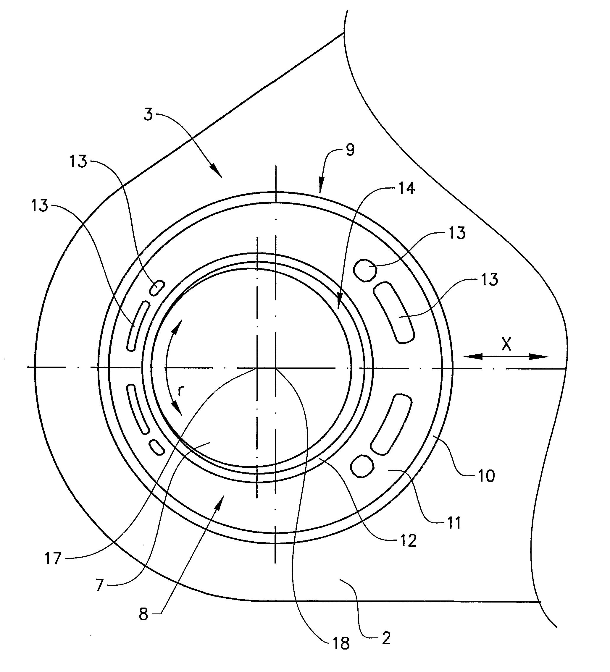
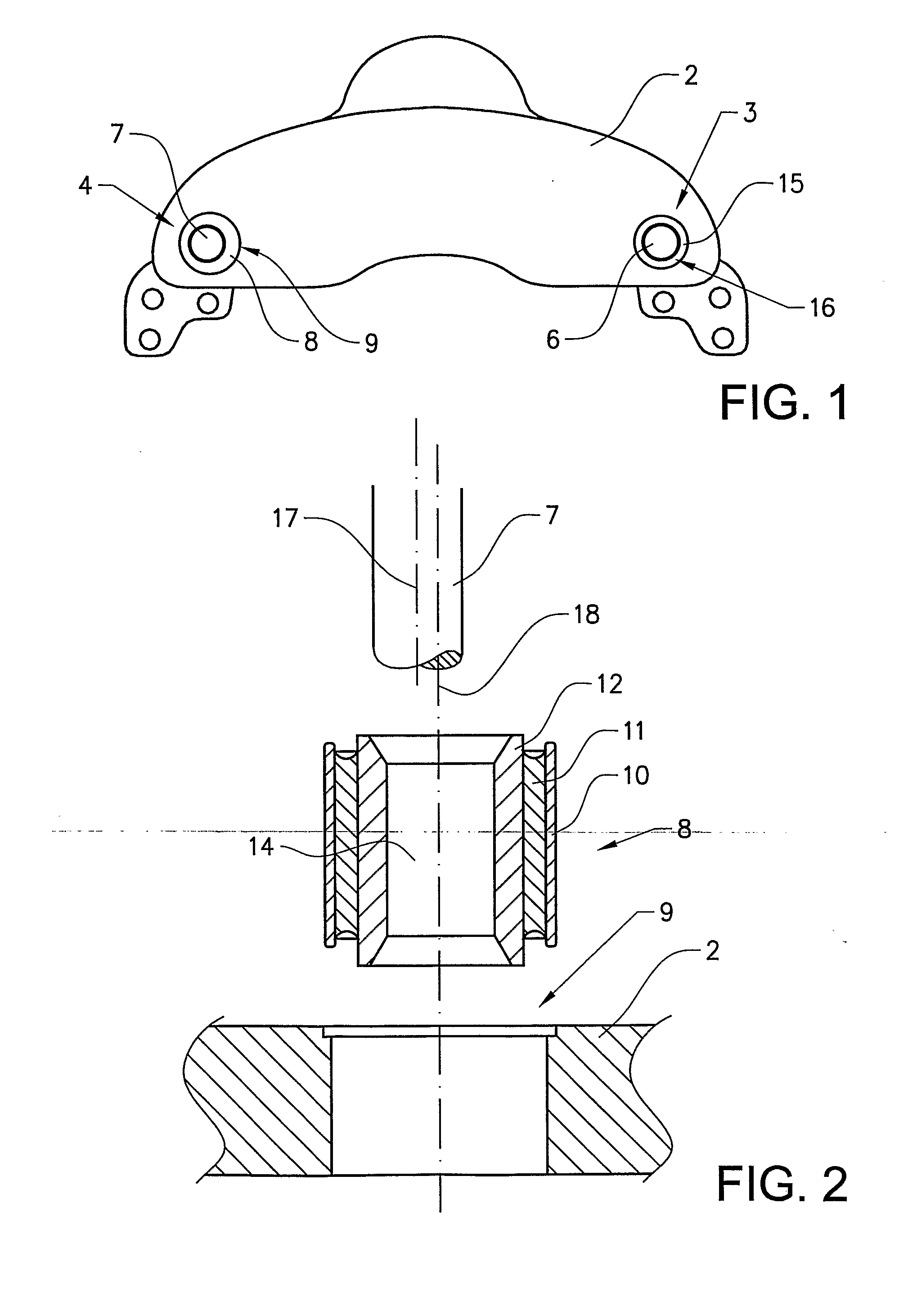
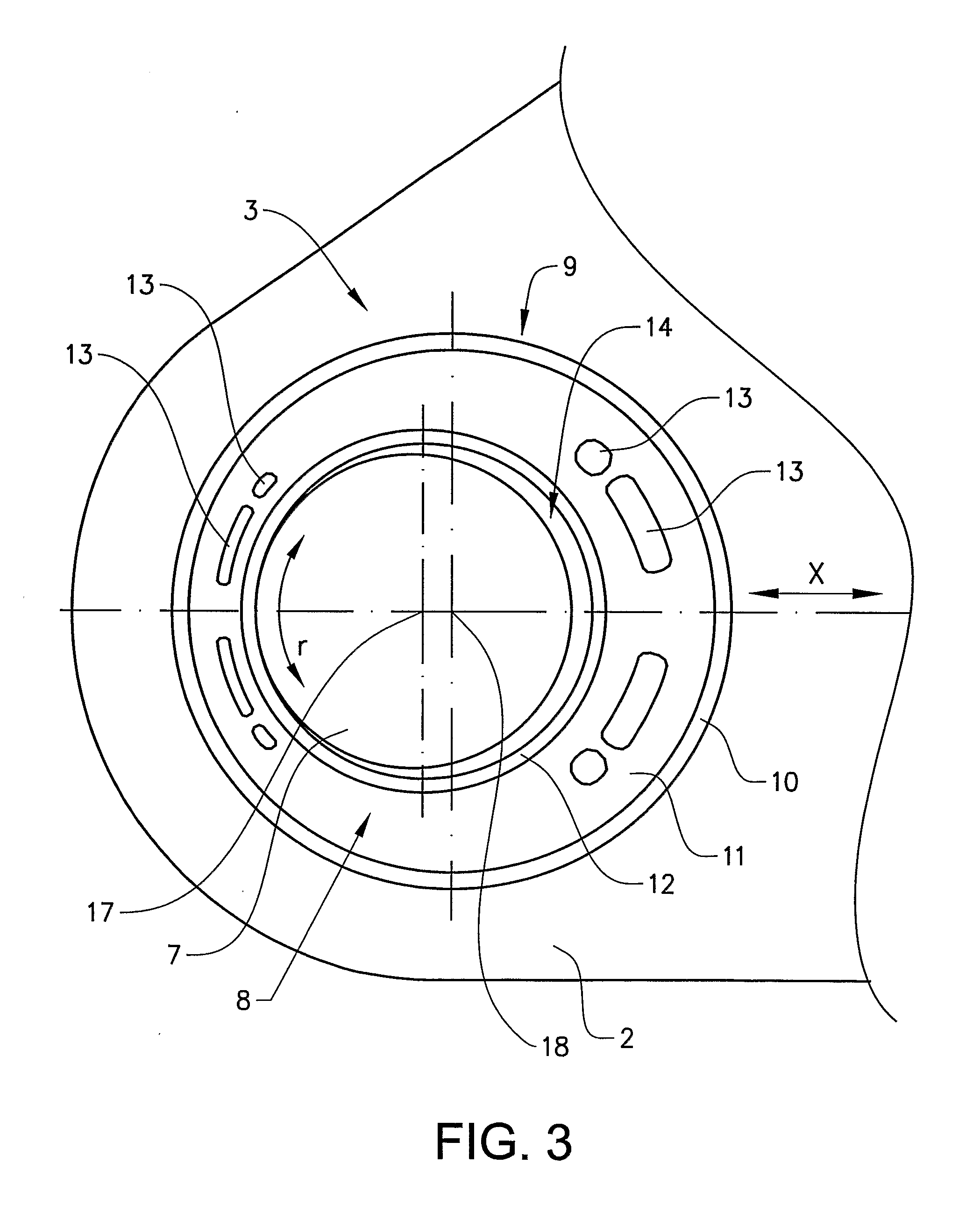
[0017]FIG. 1 shows a caliper 2 of a disk brake for a utility vehicle, in particular a truck or a bus. The caliper 2 straddles a brake disk (not shown) and the caliper 2 is displaceably fastened to the brake support (not shown) of the vehicle in a known manner.

[0018]The caliper 2 is axially displaceable along two guide pins. The caliper 2 is slidably mounted over a first support bearing 3 including the first guide pin 6 and a second support bearing 4 including the second guide pin 7. Hereby, the caliper 2 is slidably mounted on the two parallel placed guide pins 6, 7 so that the caliper 2 can slide between a first position where the brake is activated and a second position where the brake is inactive, i.e. the brake pads does not exert any pressure on the brake disk. The caliper will also slide on the guide pins to compensate for wear of the brake pads.

[0019]The first bearing 3 includes a first bushing 15 which is pressed into the bore 16 of the caliper 2. The bushing 15 is an annula...


PUM


Abstract

A sliding arrangement for a disk brake includes a caliper adapted to engage a brake disk, and a first and a second support bearing for fixing the caliper to a brake support of the vehicle so that the caliper is axially slideable relative to the brake disk, where the first support bearing includes a first guide pin and a first guide bushing and the second support bearing includes a second guide pin and a second guide bushing, where the first guide pin and guide bushing have substantially no play between their sliding surfaces and the second guide pin and guide bushing have a play between their sliding surfaces, wherein the second guide bushing include an inner and an outer annular metal member with an annular member of resilient material therebetween, and wherein the bushing is mounted such that the center of the bushing is offset to the center of the guide pin. Hereby, brake noise created by vibrations when the brake is inactive is eliminated.

Description

BACKGROUND AND SUMMARY[0001]The present invention relates to a sliding arrangement for a disk brake for a vehicle, such as a truck, a bus or the like, comprising a caliper adapted to engage a brake disk and two support bearings for fixing said caliper to a brake support of the vehicle so that the caliper is axially slidable relative to the brake disk, where a first support bearing includes a first guide pin and a first guide bushing having substantially no play and a second support bearing includes a second guide pin and a second guide bushing having a play.[0002]A disk brake of such kind is known from WO 03 / 025413 A1. A sliding disk brake includes a fixed and a floating bearing where the floating bearing includes a guide bushing having an inner opening with an oval cross-section in which a circular bearing bolt is inserted. The idea is to allow for movements of the bearing bolt in only one direction in the guide bushing. The purpose is to take up production tolerances and allow for...

Claims


Application Information

Patent Timeline
Patent Type & Authority Applications(United States)
IPC IPC(8): F16D55/227F16C33/04
CPCF16D55/22655F16D65/0012F16D55/227
Inventor BAGGE, LARSEDGREN, CLAES
Owner VOLVO LASTVAGNAR AB
Why Eureka
Try Eureka