
Welded Joint and Method for Forming the Joint

Inactive Publication Date: 2009-08-13
GM GLOBAL TECH OPERATIONS LLC
View PDF4 Cites 0 Cited by
  • Summary
  • Abstract
  • Description
  • Claims
  • Application Information

AI Technical Summary

Benefits of technology

[0007]An advantage of an embodiment is the excellent service durability of a welded joint that incorporates a collar extruded from one of the members connected by the joint. The joint requires no additional component to transition structural load between the joined members, such as a preformed collar. The joint is completed by welding the joined members mutually, thereby eliminating need for a weld between a preformed collar and one of the joined members.
[0008]Use of a preformed collar would require additional space to weld the collar to the frame rail. By avoiding the need for a preformed collar, the cross member can be located closer to the tangent of a radius formed between the caps and web of the frame rail.

Problems solved by technology

A joint formed in this way has relatively high stress in the weld, which can affect durability.
Although the welded collar provides additional structural continuity between the frame rail and the cross member by adding a third part to the joint, the weld between the collar and frame rail requires additional space, restricting the location of the cross member.
The additional collar increases the costs of components, tooling and the welding operation.

Method used


Image

  • Welded Joint and Method for Forming the Joint
  • Welded Joint and Method for Forming the Joint
  • Welded Joint and Method for Forming the Joint

Examples


Embodiment Construction

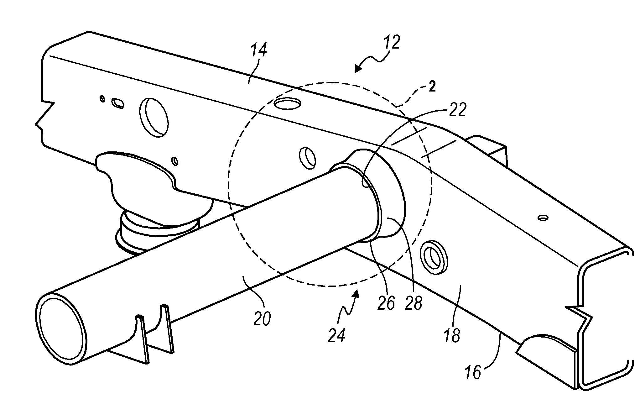
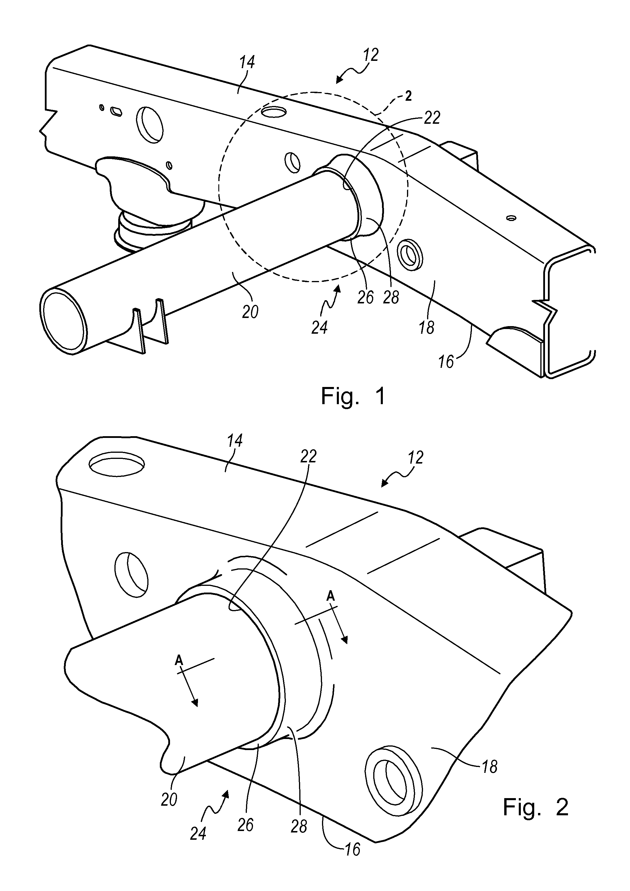
[0013]Referring to FIGS. 1 and 2, the frame of a motor vehicle includes two laterally spaced, longitudinally directed frame rails 12, on which the suspension, body, engine and powertrain are supported. The longitudinal frame rails 12 are each in the form of a beam having upper and lower flanges or caps 14, 16 and a web 18 located in a vertical plane and interconnecting the flanges.

[0014]The frame rails 12 are interconnected by a laterally directed cross member 20, which is secured to the web 18 of each of the frame rails. The cross member 20 is usually cylindrical having a circular or noncircular cross section, which is usually tubular. Generally, the frame rails 12 and the cross member 20 are formed of low alloy, sheet steel. The cross member 20 extends laterally and substantially perpendicular to the plane of the web 18, or it is inclined with respect to the web.

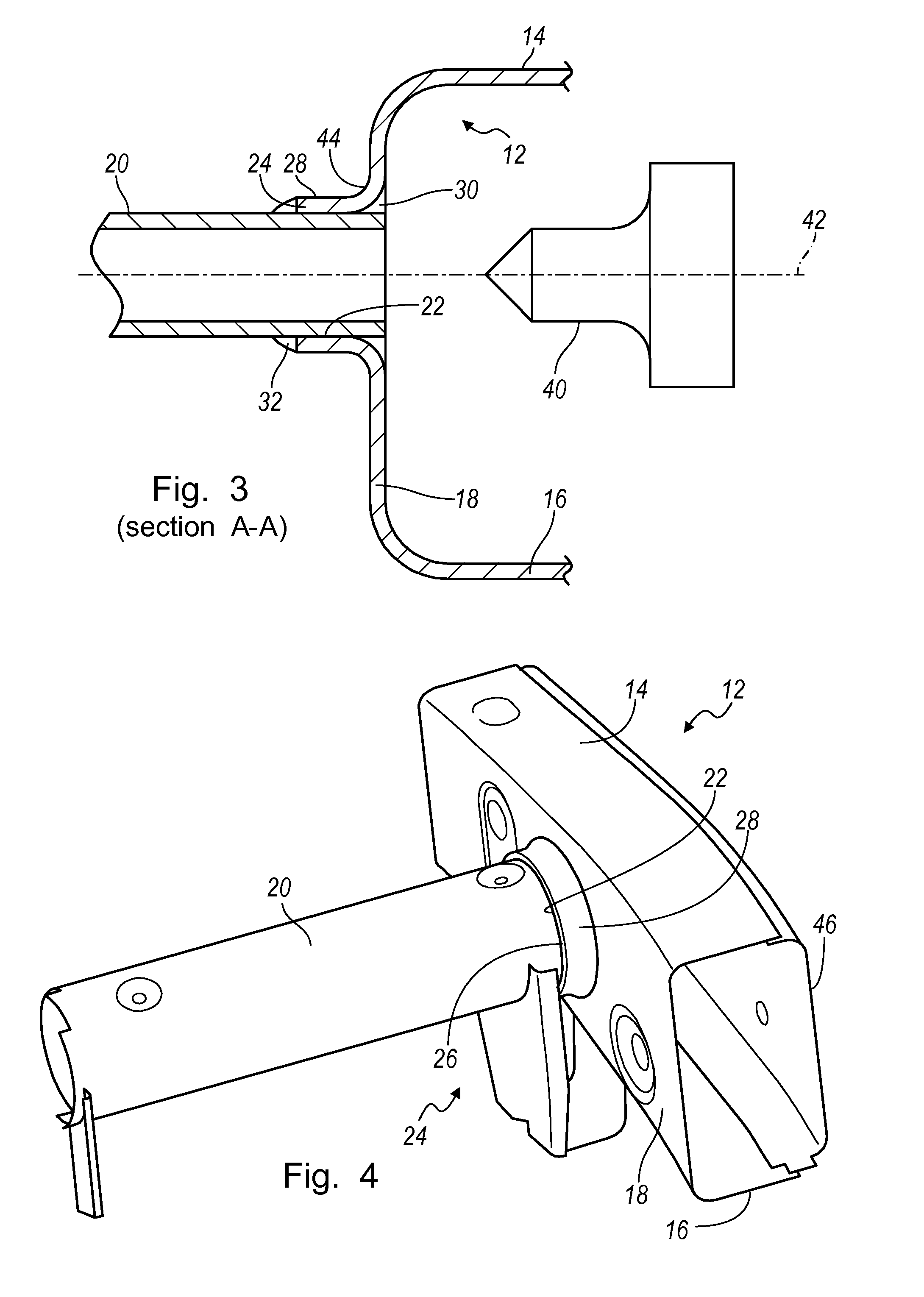
[0015]A joint for connecting the web 18 and cross member 20 includes a hole 22 formed directly in the web. The material ...


PUM

PropertyMeasurementUnit
Thicknessaaaaaaaaaa
Circumferenceaaaaaaaaaa

Abstract

A welded joint includes a cross member, a web having an extruded hole that extends through a thickness of the web and conforms to a cross sectional shape of the cross member, a collar surrounding the hole, formed from material extruded from the web in a direction such that the collar extends along the cross member and away from the web, the cross member extending through the hole and into the collar, and a weld for mutually connecting the collar and the cross member.

Description

BACKGROUND OF INVENTION[0001]The present invention relates generally to a vehicular chassis, and, more particularly, to joining a cross member to a frame rail, such as a vehicle frame.[0002]The chassis of a motor vehicle includes two laterally spaced, longitudinally directed frame members, on which the suspension, engine and powertrain are supported. The frame rails are in the form of a closed or open section beam having upper and lower flanges or caps, and one or two webs interconnecting the flanges. The frame rails are interconnected by laterally directed cross members, which are secured to the web of each of the frame rails. The cross members are usually cylindrical having a circular or noncircular cross section, which is usually tubular but may be a non-tubular solid, such as a rod. Generally, the frame rails and the cross members are formed of sheet steel.[0003]The cross members may be joined to the web of the frame rails by punching or drilling a hole in the web, inserting the...

Claims


Application Information

Patent Timeline
IPC IPC(8): F16B9/02B62D21/06B23K35/12
CPCB62D21/02Y10T403/479B62D27/023
Inventor PESCHANSKY, LEN V.SARTI, PAOLO V.BURGER, FRANKVON KNORRING, DAVID L.
Owner GM GLOBAL TECH OPERATIONS LLC
Learn More