Systems and Methods for Receiving and Managing Power in Wireless Devices

a wireless device and wireless technology, applied in the direction of transportation and packaging, d ac network circuit arrangement, etc., can solve the problems of time-consuming and expensive task of periodically replacing the battery, rfid tags typically only operate over short distances, and the battery life of such sensors often requires additional surgical procedures

Inactive Publication Date: 2009-08-13
UNIV OF COLORADO THE REGENTS OF
View PDF5 Cites 362 Cited by
  • Summary
  • Abstract
  • Description
  • Claims
  • Application Information

AI Technical Summary

Benefits of technology

[0007]In one embodiment, a radio frequency (RF) reception device has a first periodic or aperiodic antenna array with one or more antenna elements. Electrical conductors provide connectivity of the antenna elements such t

Problems solved by technology

The lifetime of the battery used within such a sensor often requires additional surgical procedures to periodically replace the battery.
Similarly, where a sensor and transmitting device is located within controlled or hazardous environments, it is often a time-consuming and expensive task to periodically replace the battery.
One drawback of this te

Method used


Image

  • Systems and Methods for Receiving and Managing Power in Wireless Devices
  • Systems and Methods for Receiving and Managing Power in Wireless Devices
  • Systems and Methods for Receiving and Managing Power in Wireless Devices

Examples


Embodiment Construction

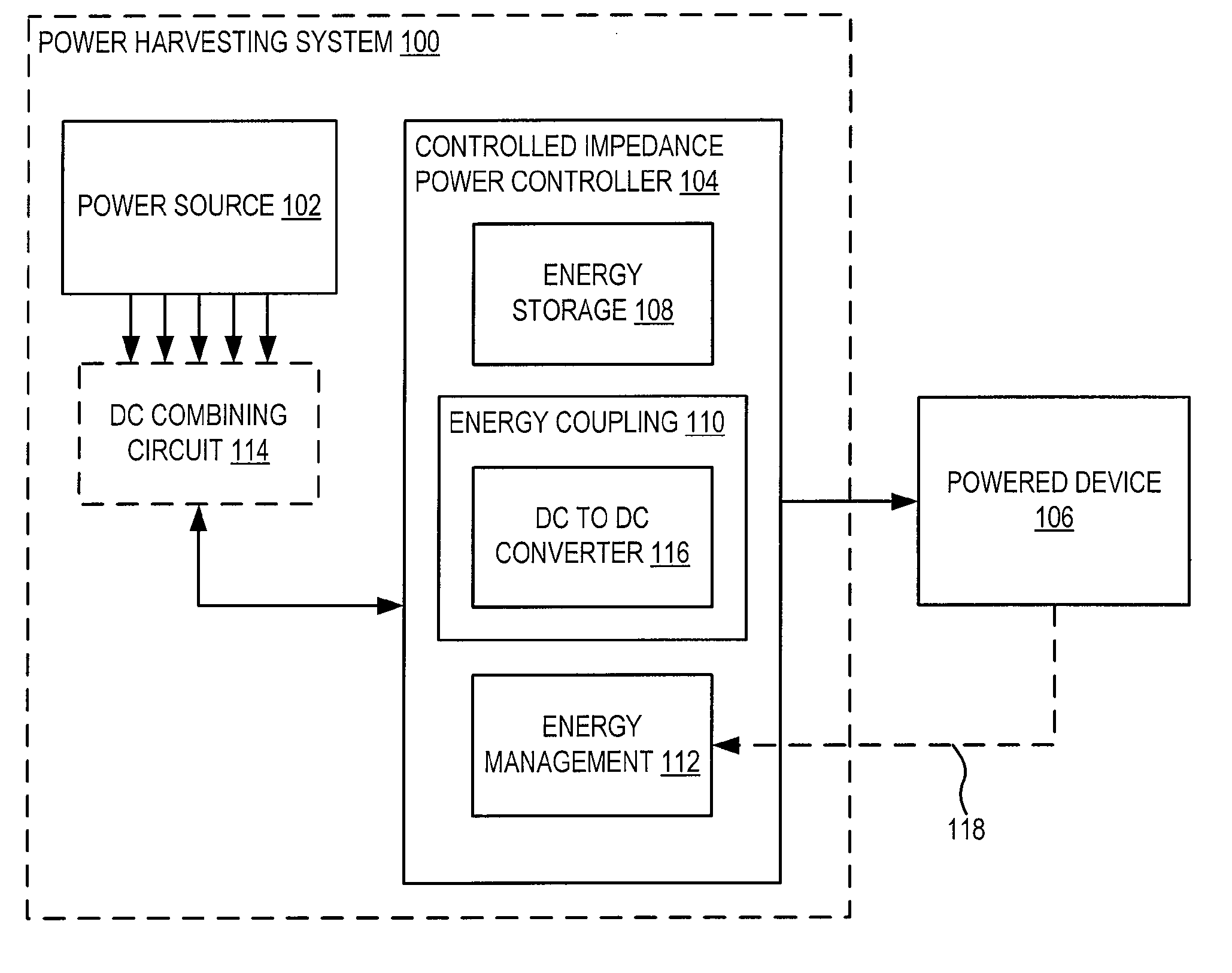
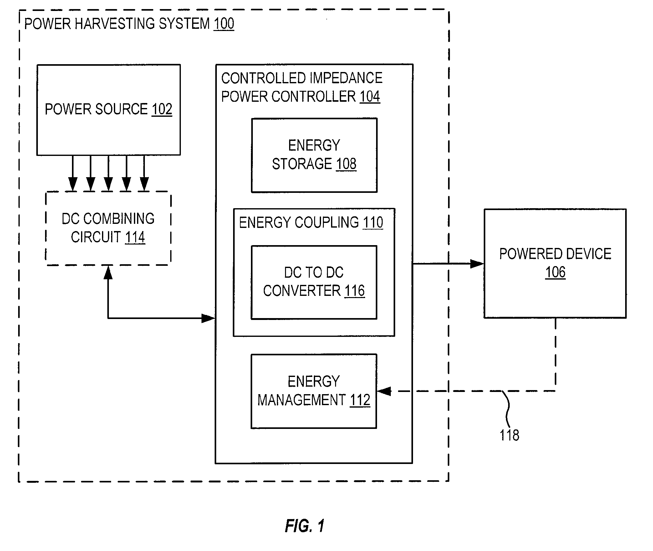
[0046]FIG. 1 shows an embodiment of a power collecting system 100 that includes power sources 102 and a controlled impedance, voltage or current power controller 104. Power harvesting system 100 is illustratively shown powering a powered device 106. Powered device 106 is, for example, a sensor and / or transceiver device. Power source 102 may represent one or more of: a rectenna, a photovoltaic cell, a piezoelectric device or other power collecting device. Although described in various embodiments as a power collecting system or a power harvesting system, it should be understood that the systems, devices and methods described herein may be used for either purpose.

[0047]Power controller 104 is illustratively shown with energy storage device 108, energy coupling device 110 and energy management device 112. Energy storage device 108 is for example a battery or a capacitor; it may be internal to power controller 104, as shown, or external to power controller 104 without departing from the...


PUM


Abstract

Exemplary systems and methods are provided for collecting/harvesting direct current (DC) power received from a power source(s). The system comprises a controlled impedance power controller comprises a power converter configured to present a positive equivalent resistive load to the at least one power source over a range of input power levels. Exemplary systems and methods are provided for collecting radio frequency (RF) power. An exemplary system comprises at least two rectenna elements, a power controller, and a DC combining circuit. The DC combining circuit is associated with the at least two rectenna elements and the DC combining circuit is configured to dynamically combine the at least two rectenna elements in one of a plurality of series/parallel configurations. The power controller is configured to control the DC combining circuit to achieve a desired overall power output from the at least two rectenna elements.

Description

CROSS-REFERENCE TO RELATED APPLICATIONS[0001]This application claims priority to U.S. Provisional Patent Application Ser. No. 60 / 729,378 filed Oct. 21, 2005, U.S. Provisional Patent Application Ser. No. 60 / 760,040, filed Jan. 17, 2006, and PCT Application Number PCT / US2006 / 041355, filed Oct. 23, 2006, all incorporated herein by reference.FIELD OF INVENTION[0002]This application relates generally to systems and methods for receiving and managing power in wireless devices, and more particularly, to systems and methods for harvesting and / or collecting RF power and / or for converting direct current power.BACKGROUND OF THE INVENTION[0003]Sensors and transmitters that are small and require low levels of power for operation are frequently used for collecting information without being intrusive to their operating environment. For example, a battery powered sensing and transmitting device may be surgically implanted within living tissue to sense and transmit characteristics of the body in whi...

Claims


Application Information

Patent Timeline
IPC IPC(8): H02J7/00H02J1/00H01Q5/42
CPCH01Q1/2225H01Q5/42H01Q1/248H02J50/12H02J50/20
Inventor ZANE, REGANPOPOVIC, ZOYASHARP, ANDREWRESTREPO, DIEGO
Owner UNIV OF COLORADO THE REGENTS OF
Why Eureka
Try Eureka