Fiber optic security system for sensing the intrusion of secured locations

a security system and fiber optic technology, applied in the direction of optical radiation measurement, counting objects on conveyors, instruments, etc., can solve the problems of not using fiber optics, system is not suitable for detecting events in a wide geographical area, and system is not suitable for wide area security systems

Inactive Publication Date: 2009-08-13
WOVEN ELECTRONICS
View PDF19 Cites 18 Cited by
  • Summary
  • Abstract
  • Description
  • Claims
  • Application Information

AI Technical Summary

Problems solved by technology

However, the system does not use fiber optics, requires electrical power at the location, and is generally not suited for a wide area security system.
However, this system requires physical connection of the optic fiber to the appliance and the system is not suitable for detecting events in a wide geographical area.
Here again, the system requires physical connection to the moveable part of the fence and the fiber optic cable requires electrical power at the location, and is generally not suitable for wide geographical areas.
Not only do the above security systems and sensors require a physical connection between the optic fiber and the moveable member, but the systems require electrical power at the location sought to be protected making them wholly unsuitable for many security applications, including wide geographical area systems.
More importantly, no provision is made for identifying the location of an intrusion event where large numbers of sensors are utilized.

Method used


Image

  • Fiber optic security system for sensing the intrusion of secured locations
  • Fiber optic security system for sensing the intrusion of secured locations
  • Fiber optic security system for sensing the intrusion of secured locations

Examples


Embodiment Construction

[0029]Referring now to the drawings, the invention will now be described in more detail.

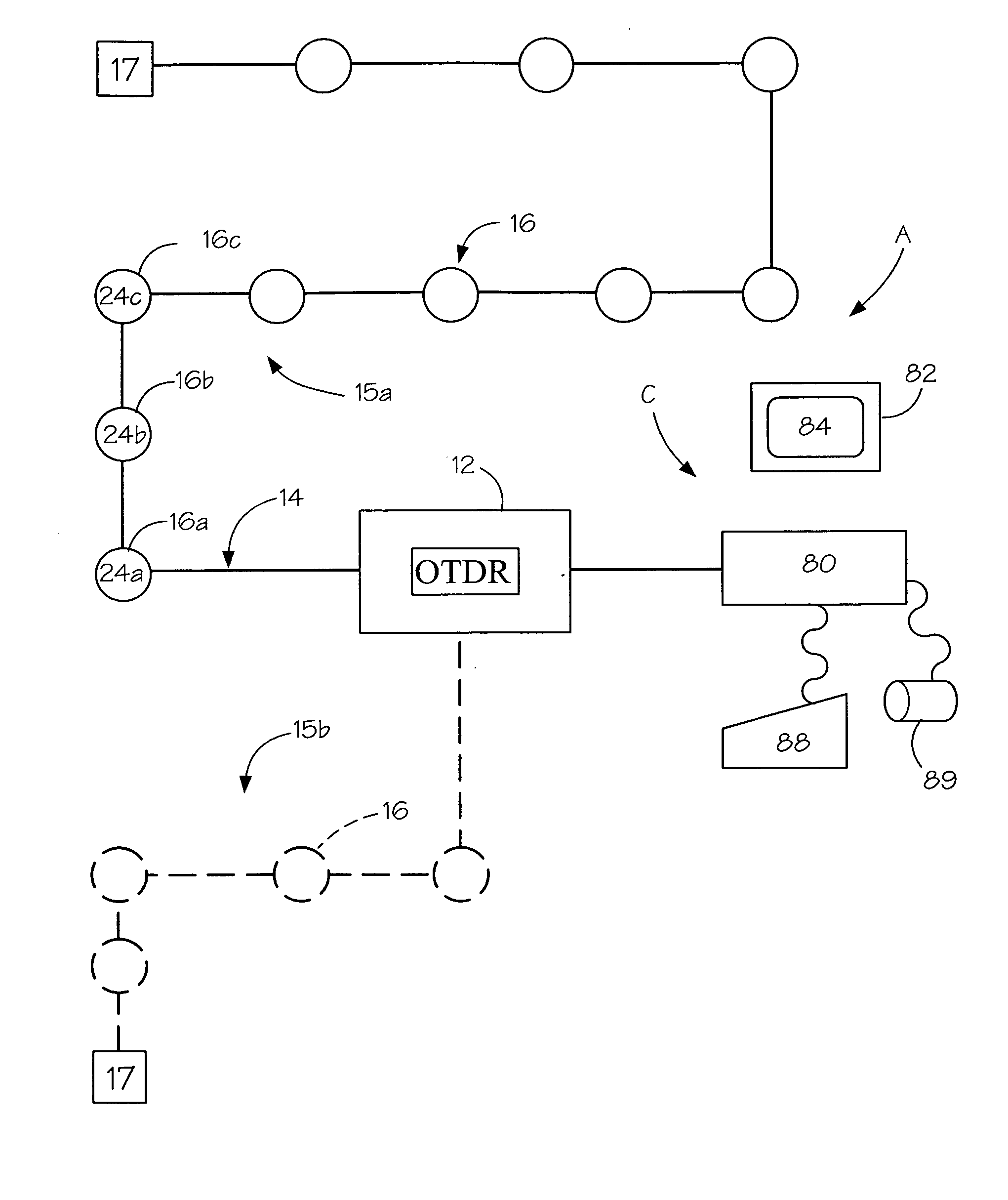
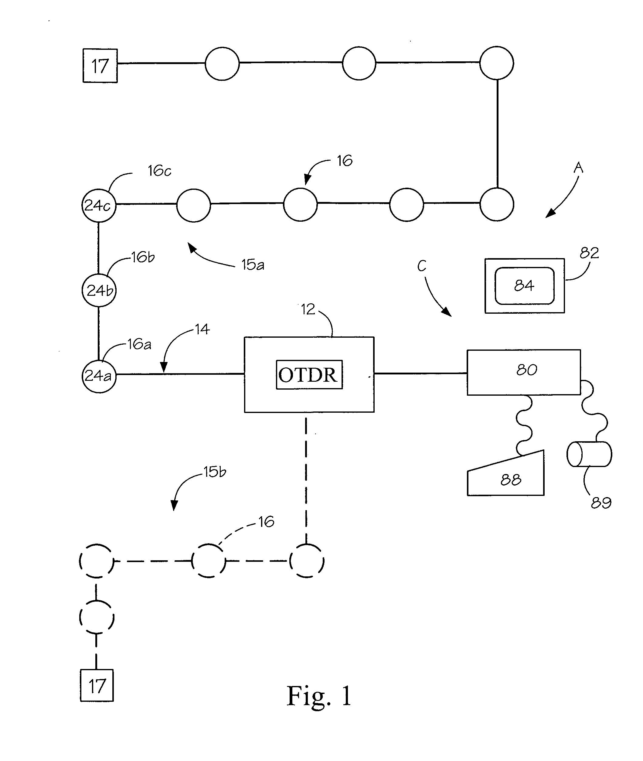
[0030]As can best be seen in FIG. 1, an optical fiber security system, designated generally as A, is illustrated. The security system includes a remote processor, designated generally as 10, for processing an intrusion signal to determine the occurrence and location of the intrusion. The processor may, for example, include an optical time domain reflectometer (OTDR) 12 of the type routinely utilized to monitor maintenance of fiber optic network systems. Typically, the OTDR is used to sense a fiber breakage, water seepage, irregular bends, or other defects in one or more optical fibers of the fiber network along the routing path of the network. For example, in large municipalities it is not uncommon for there to be 1,000 miles of fibers in an optical fiber network. However, as opposed to these conventional uses, an expedient of the present invention is to utilize the OTDR to detect the occurrence ...


PUM


Abstract

A sensor for a security system is disclosed to detect intrusions at one or more predetermined locations wherein each location includes a moveable member which must be moved in order to intrude the location. The system includes a fiber network routed in close proximity to one or more locations. The sensor comprises a sensor housing for being disposed at a location to detect a predetermined movement of the moveable member from a secure position to an unsecured position, and means for mounting the sensor housing in a stationary position at the location without a physical connection to the moveable member. The sensor housing includes a fiber inlet and a fiber outlet, and a fiber chamber for receiving a predetermined sensor fiber of the fiber network being routed through the sensor housing. The sensor has a sensor actuator for engaging the sensor fiber to generate an intrusion signal upon detecting predetermined movement of the moveable member, and causing the intrusion signal to be transmitted along the sensor fiber to a processor whereby the intrusion and location of the intrusion may be determined by the processor. Preferably, the sensor includes a magnetic actuator having a magnetic attraction to the moveable members whose interruption causes activation of the sensor and generation of the intrusion signal.

Description

BACKGROUND OF THE INVENTION[0001]This invention relates to a fiber optic security system and sensor for detecting the intrusion of a secured location and, more particularly, to such a system and sensor wherein each secured location includes a moveable member which secures the location and a fiber optic network routed in close proximity to the location wherein the sensor senses movement of the moveable member to an unsecured position, and the system detects the occurrence and location of the intrusion.[0002]With the increase in terrorist events needed to be prevented in the United States, the need for effective security systems to sense intrusion into secured areas has greatly increased. In particular, a security system for the protection of a vast system of underground utilities accessed by manholes with removeable covers is needed. A highly effective system to detect entrance into these underground spaces and utilities is needed in order to protect against vandalization and terrori...

Claims


Application Information

Patent Timeline
Patent Type & Authority Applications(United States)
IPC IPC(8): G08B13/24G08B13/00
CPCG08B13/186G08B13/124G08B13/08E02D29/1481H02G9/10
Inventor BROWNING, JR., THOMAS E.PHILLIPS, MARK C.
Owner WOVEN ELECTRONICS
Why Eureka
Try Eureka