Fundus photo-stimulation system and method

a photo-stimulation system and fundus technology, applied in the field of optical systems and methods, can solve the problems that local photo-stimulation systems that can be used in conjunction with readily available fundus-observation systems such as fundus cameras are not currently availabl

Inactive Publication Date: 2009-08-13
UNITED STATES OF AMERICA
View PDF10 Cites 17 Cited by
  • Summary
  • Abstract
  • Description
  • Claims
  • Application Information

AI Technical Summary

Problems solved by technology

Such local photo-stimulation systems that can be used in conjunction with readily ...

Method used


Image

  • Fundus photo-stimulation system and method
  • Fundus photo-stimulation system and method
  • Fundus photo-stimulation system and method

Examples


Embodiment Construction

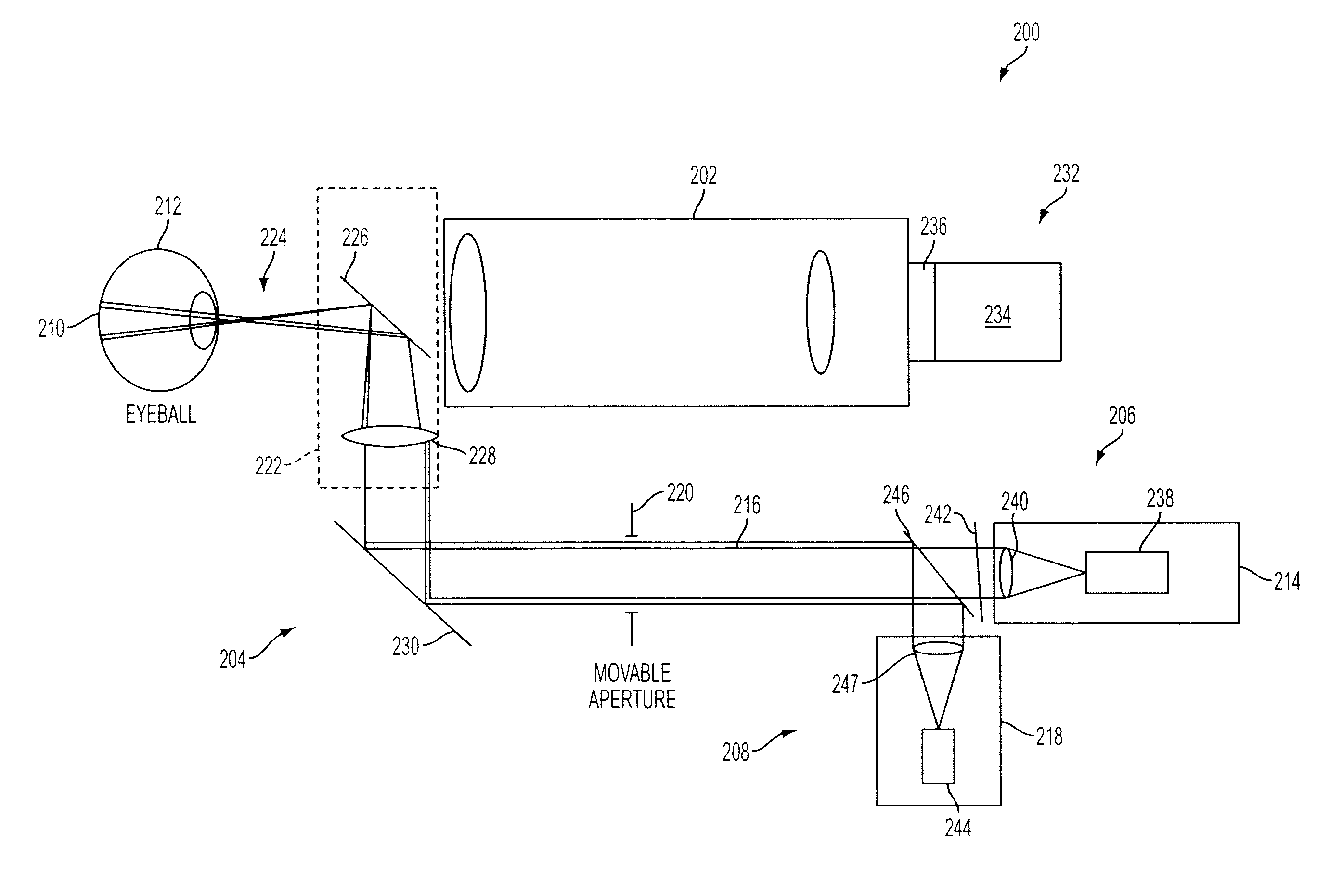
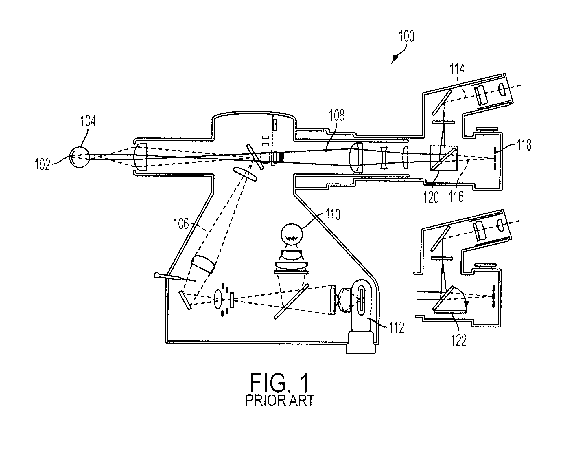
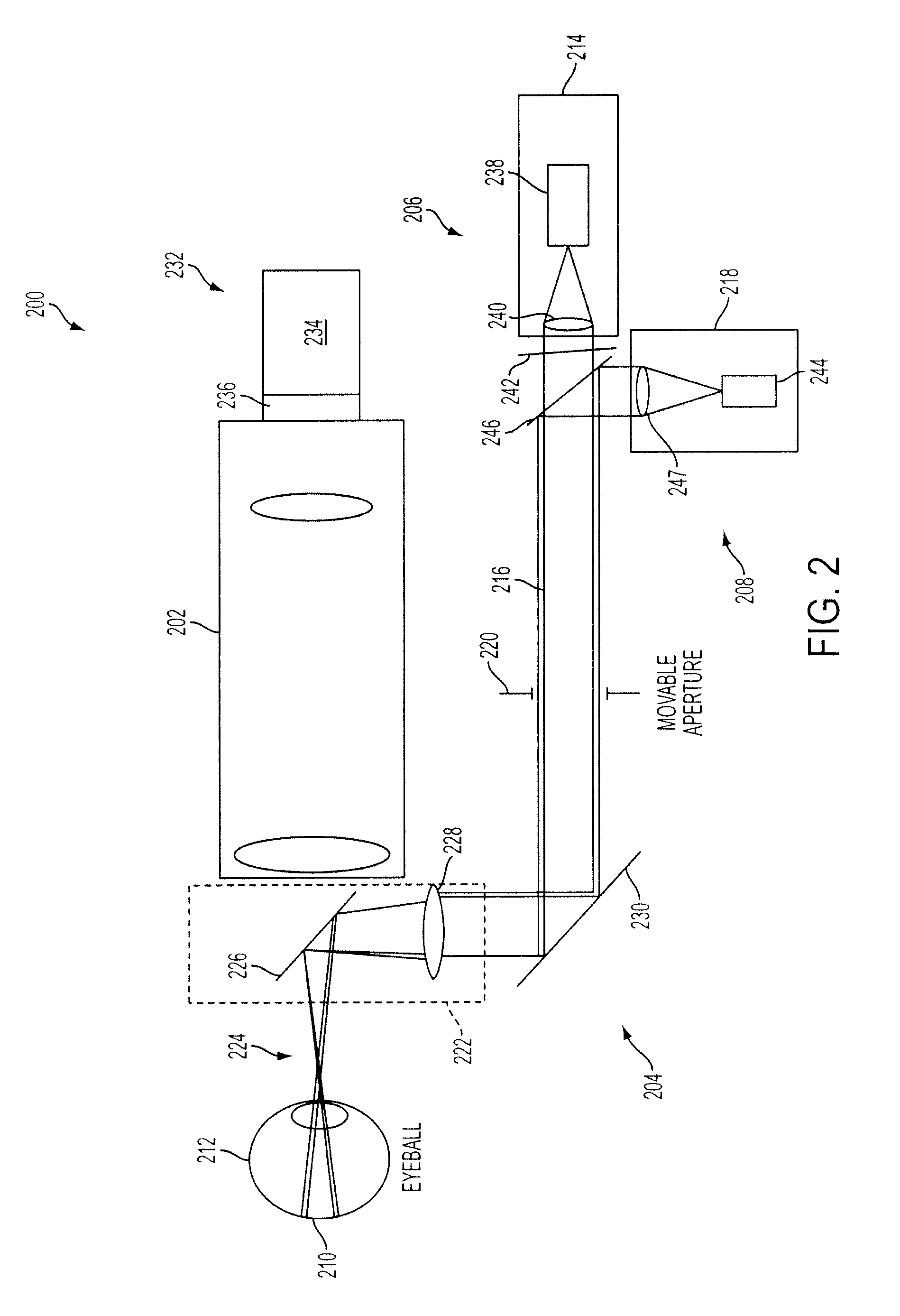
[0018]An optical system according to embodiments of the current invention can be used to provide illumination of the retina using Maxwellian-view principles and providing photo-stimulation of selected regions under continuous visualization of the region being stimulated. The system can be readily integrated into commercial fundus cameras in some embodiments of the current invention, despite that such devices do not operate using Maxwellian-view optics. For example, it has been integrated with an F4 fundus camera manufactured by Zeiss in an embodiment of the current invention. Two fiber-optically coupled light systems (a targeting 670 nm laser, whose deep red output alternates on and off at 1 Hz, and a Xenon flash lamp or a 488 nm Argon laser, whose shorter wavelength output is delivered as brief flashes) are brought into co-linear alignment and arranged to enter the eye co-axially with the optical axis of the imaging fundus camera in this embodiment of the invention. The two beams a...


PUM


Abstract

An eye examination device has a fundus observation system and an optical stimulation system. The optical stimulation system has an optical targeting subsystem and an optical stimulation subsystem, wherein the optical stimulation system is structured to be used to provide light stimulation to a portion of a fundus of an eye targeted by the optical targeting subsystem in conjunction with observations made with the fundus observation system.

Description

BACKGROUND[0001]1. Field of Invention[0002]The present invention relates to optical systems and methods, and more particularly to optical systems and methods to photo-stimulate selected portions of the fundus of an eye.[0003]2. Discussion of Related Art[0004]Instruments are available to view and photograph the fundus of a patient's eye. For example, one such instrument in wide use is a fundus camera. FIG. 1 is an example of a conventional fundus camera 100. The fundus camera 100 is one example of an optical system to observe the fundus 102 of a subject's eye 104. The fundus camera 100 has an illumination path 106 and a viewing path 108. A constant illumination may be provided by an incandescence light bulb 110, for example. A brighter flash illumination may be provided by flash bulb 112 for use in conjunction with film-based cameras. Furthermore, the viewing path 108 may be split into a path for direct viewing 114 by a user and a path 116 to a camera 118 for photographing an image o...

Claims


Application Information

Patent Timeline
IPC IPC(8): A61B3/12A61B3/14
CPCA61B3/14A61B3/12
Inventor SMITH, PAUL D.DE MONASTERIO, FRANCISCOWELLNER, EDWARD
Owner UNITED STATES OF AMERICA
Why Eureka
Try Eureka