Exposure Method and Apparatus

a technology which is applied in the field of exposure method and exposure apparatus, can solve the problems of high production cost, high cost of performing the exposure method using the highly precise mask, and high production cost, so as to reduce the exposure amount, increase the exposure amount, and reduce the exposure amount

Inactive Publication Date: 2009-08-13
FUJIFILM CORP
View PDF17 Cites 17 Cited by
  • Summary
  • Abstract
  • Description
  • Claims
  • Application Information

AI Technical Summary

Benefits of technology

[0057]As described above, in the second exposure apparatus and the third exposure apparatus according to the present invention, exposure of the photosensitive material is separately controlled in a forward movement and in a backward movement. Therefore, it is possible to increase or decrease the exposure amount for exposing the surface of the photosensitive material, which has been produced by applying a multilayered photosensitive layer, without changing the number of light sources. Further, it is also possible to expose the photosensitive material to light to form an image of a high-sensitivity portion (for example, an image of a print pattern portion, which requires high resolution) and an image of a low-sensitivity portion (for example, an image of a through-hole portion, in which protection of the inner wall and the edge thereof with copper foil is required). The second exposure apparatus and the third exposure apparatus according to the present invention can achieve such excellent advantageous effects.
[0058]Further, in the second exposure apparatus or the third exposure apparatus, the light amount of a light beam emitted from the exposure head may be constant, and the exposure control means may control exposure so that sub-scan speed (the speed of relative movement by the exposure head and the photosensitive material in the sub-scan direction) in the forward movement and the sub-scan speed in the backward movement are different from each other. Especially, if the second exposure apparatus or the third exposure apparatus is structured, as described above, even if the light amount of the light beam emitted from the exposure head is constant, it is possible to expose the second photosensitive layer to light at a lower exposure amount by increasing sub-scan speed to reduce the exposure amount. Further, it is also possible to expose the first photosensitive layer to light at a higher exposure amount by reducing the sub-scan speed to increase the exposure amount. Here, when the first photosensitive layer is exposed to light, the second photosensitive layer, on which the first photosensitive layer is superposed, is also exposed to light.
[0059]Therefore, if the sub-scan speed is changed so that the sub-scan speed in the forward movement and the sub-scan speed in the backward movement are different from each other in relative movement by the exposure head and the photosensitive material, it is possible to increase or decrease the exposure amount at the photosensitive material without increasing or decreasing the number of light sources.
[0060]Further, in the second exposure apparatus or the third exposure apparatus, sub-scan speed, at which the exposure head and the photosensitive material move relative to each other in the sub-scan direction, may be constant through the forward movement and the backward movement. Further, the exposure control means may control exposure of each of the first photosensitive layer and the second photosensitive layer so that the light amount of the light beam emitted from the exposure head becomes a maximum light amount during exposure of the first photosensitive layer and the light amount of the light beam becomes 1 / n (n is a positive integer) of the maximum light amount during exposure of the second photosensitive layer. Especially, if the second exposure apparatus or the third exposure apparatus is structured, as described above, even if the sub-scan speed is constant through the forward movement and the backward movement, the exposure control means can increase the light amount of the light beam emitted from the exposure head to the maximum value so as to increase the exposure amount when the first photosensitive layer is exposed to light in a pattern based on image data. Accordingly, the low-sensitivity first photosensitive layer can be more quickly exposed to light.
[0061]Meanwhile, when the second photosensitive layer is exposed to light in a pattern based on image data, the exposure amount may be reduced, for example, by reducing the light amount of the light beam to 1 / n (n is a positive integer) of the maximum light amount by a filter or the like which is set in the exposure head. Accordingly, only the second photosensitive layer is exposed to light. If the light amount of light emitted from the exposure head is reduced, it is possible to reduce the exposure amount without reducing the number of light sources.
[0062]Therefore, even if the sub-scan speed is constant through the forward movement and the backward movement in the forward / backward movement by the exposure head and the photosensitive material, it is possible to increase or reduce the exposure amount in exposure of the photosensitive material. The exposure amount can be increased or reduced by increasing or reducing the light amount of the light beam without changing the number of the light sources.

Problems solved by technology

However, since a highly precise mask is extremely expensive, the cost for performing the exposure method using the highly precise mask inevitably becomes high.
In this method, since the structure becomes complex, there is a problem that the production cost becomes high.
In that case, the exposure power may be wasted in an optical system, such as a DMD, which uses illumination light.
Therefore, the data processing amount increases several times, and there is a problem that it is difficult to maintain the processing speed.

Method used


Image

  • Exposure Method and Apparatus
  • Exposure Method and Apparatus
  • Exposure Method and Apparatus

Examples


Embodiment Construction

[0166]Hereinafter, an embodiment of the present invention will be described with reference to the attached drawings.

[Structure of Exposure Apparatus]

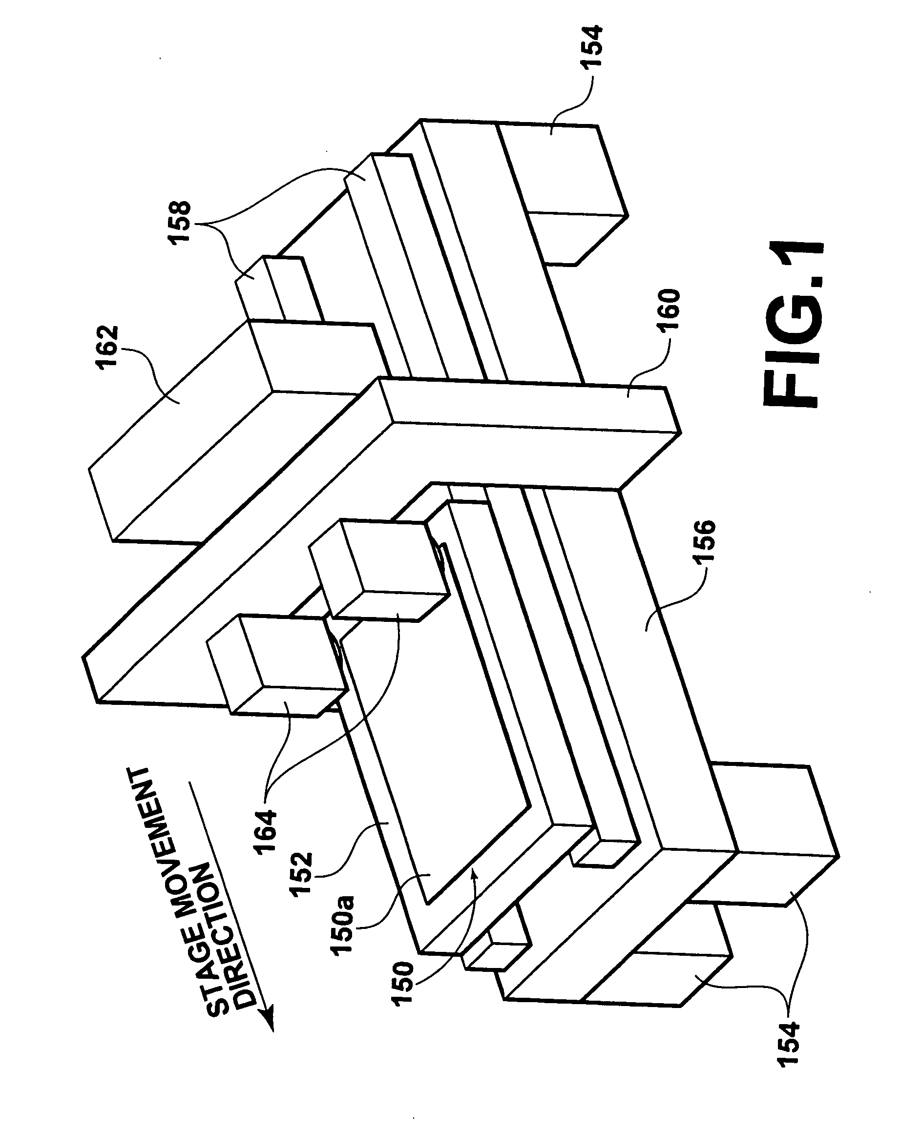
[0167]As illustrated in FIG. 1, an exposure apparatus according to the present invention includes a flat-plate-shaped moving stage 152 which holds a glass substrate 150 on the surface thereof by suction. A thin coating of photoresist 150a has been applied to the surface of the glass plate 150. Further, two guides 158 extending along the movement direction of the stage 152 are provided on the upper surface of a base 156. The base 156 has a shape of a thick flat plate and it is supported by four legs 154a. The stage 152 is placed in a manner that the longitudinal direction thereof is arranged in the movement direction of the stage 152, and the stage 152 is supported by the guides 158 in a manner that allows forward and backward movement of the stage 152. Further, a stage drive device 304 (please refer to FIG. 15), which will be described ...


PUM


Abstract

A photosensitive material (for example, a glass substrate coated with a photoresist) is exposed to light in a predetermined pattern by illuminating the photosensitive material with exposure light by an exposure head which emits light that has been modulated by a spatial light modulation device. The exposure head and the photosensitive material are moved in a sub-scan direction at least twice for each photosensitive material. The operation of the spatial light modulation device is controlled in each of sub-scan movements to form an exposed area, of which the exposure amount is at least at two different levels, in the photosensitive material.

Description

TECHNICAL FIELD[0001]The present invention relates to an exposure method and an exposure apparatus. Particularly, the present invention relates to an exposure method and an exposure apparatus for exposing a photosensitive material, such as a photoresist, to light in a predetermined pattern by illuminating the photosensitive material with light modulated by a spatial light modulation device.BACKGROUND ART[0002]Conventionally, in production of a TFT (thin film transistor) for an LCD (liquid crystal display), a photolithography (hereinafter, referred to as photolitho) process is widely adopted. Basically, in the photolitho process for producing the TFT or the like, a thin photoresist coating is applied to a glass substrate on which a coating of metal or semiconductor has been formed. The photoresist is exposed to exposure light which is transmitted through a mask in which a predetermined pattern is formed. Then, the photoresist is developed to form a predetermined resist pattern.[0003]...

Claims


Application Information

Patent Timeline
Patent Type & Authority Applications(United States)
IPC IPC(8): G03B27/72G03B27/32
CPCG03F7/70275G03F7/70791G03F7/70358G03F7/70291G02B26/0833
Inventor OZAKI, TAKAOKITAGAWA, TOMOYA
Owner FUJIFILM CORP
Why Eureka
Try Eureka