Surface light source device

a surface light source and light-converging technology, which is applied in the direction of fixed installation, lighting and heating equipment, instruments, etc., can solve the problems of reduced optical efficiency, large required optical sheets, poor light-converging properties of conventional surface light-converging devices, etc., to reduce luminance non-uniformity and color non-uniformity, the effect of reducing the luminance non-uniformity

Inactive Publication Date: 2009-08-13
DAI NIPPON PRINTING CO LTD
View PDF7 Cites 20 Cited by
  • Summary
  • Abstract
  • Description
  • Claims
  • Application Information

AI Technical Summary

Benefits of technology

[0022]In this case, the reflective layer diffuses and reflects light that has been reflected and returned from the lenticular lens sheet (14-1, 14-2), whereby the light can again enter the lenticular lens sheet (14-1, 14-2) at a different incident angle and at a different incident position. Therefore, the function of reducing the luminance non-uniformity and the color non-uniformity can be further improved.
[0023]In addition, preferably, a reflectivity with respect to light vertically incident on the lenticular lens sheet (14-1, 14-2) is not less than 40%. In this

Problems solved by technology

Such a conventional surface light source device is poor in the light-converging properties, although the number of required optical sheets is large.
However, this improvement suffers reduction in optical efficiency, and complicates the structure of the LCD panel, which results in increase in cost.
In particular, the light intensity (luminance) tends to be non-uniform (luminance non-uniformity tends to occur) depending on the distance from the cold-cathode tubes (i.e., whether that point is close to a certain cold-cathode tube or to a space between the cold-cathode tubes arranged in parallel).
However, t

Method used


Image

  • Surface light source device
  • Surface light source device
  • Surface light source device

Examples


first embodiment

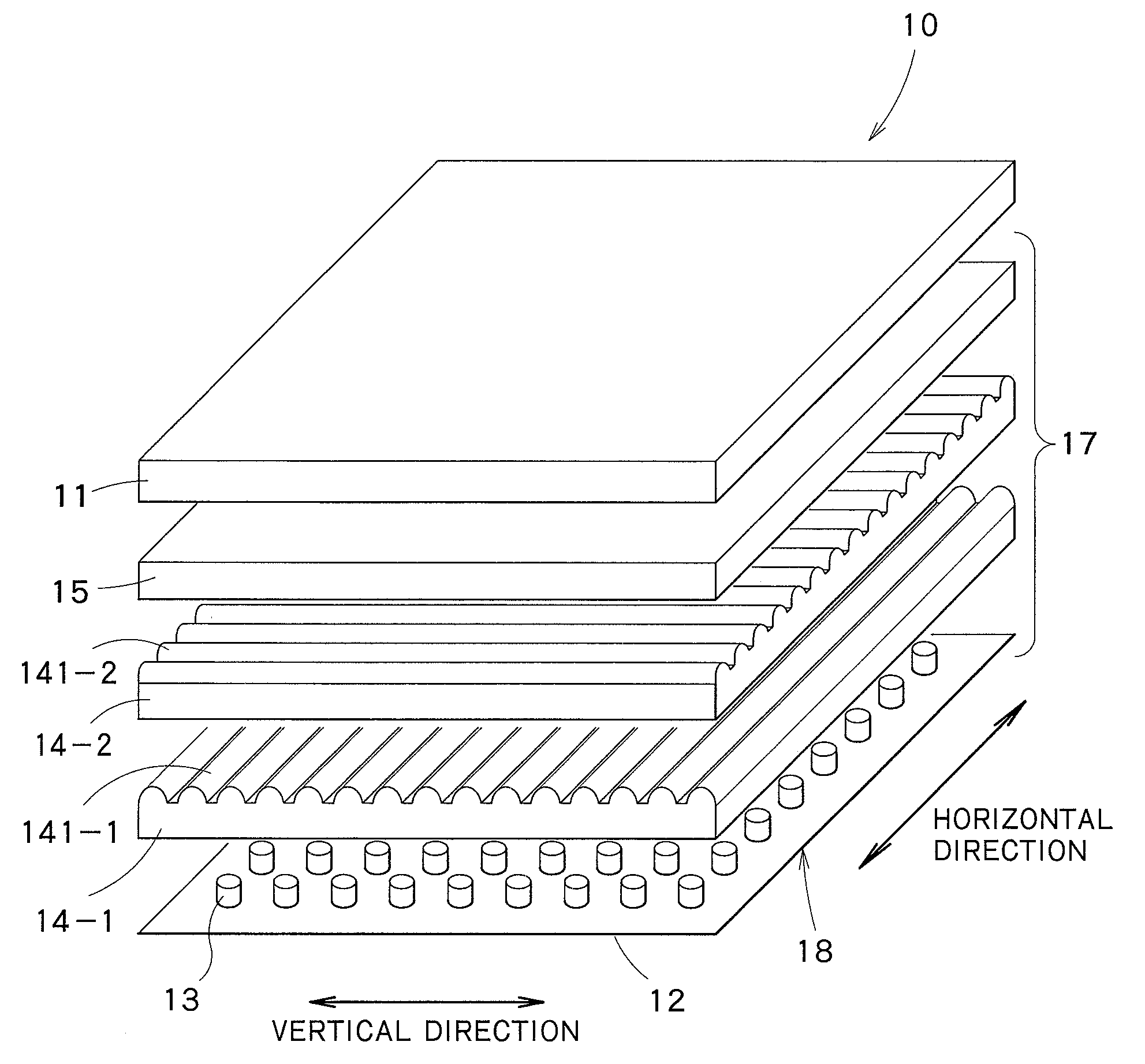
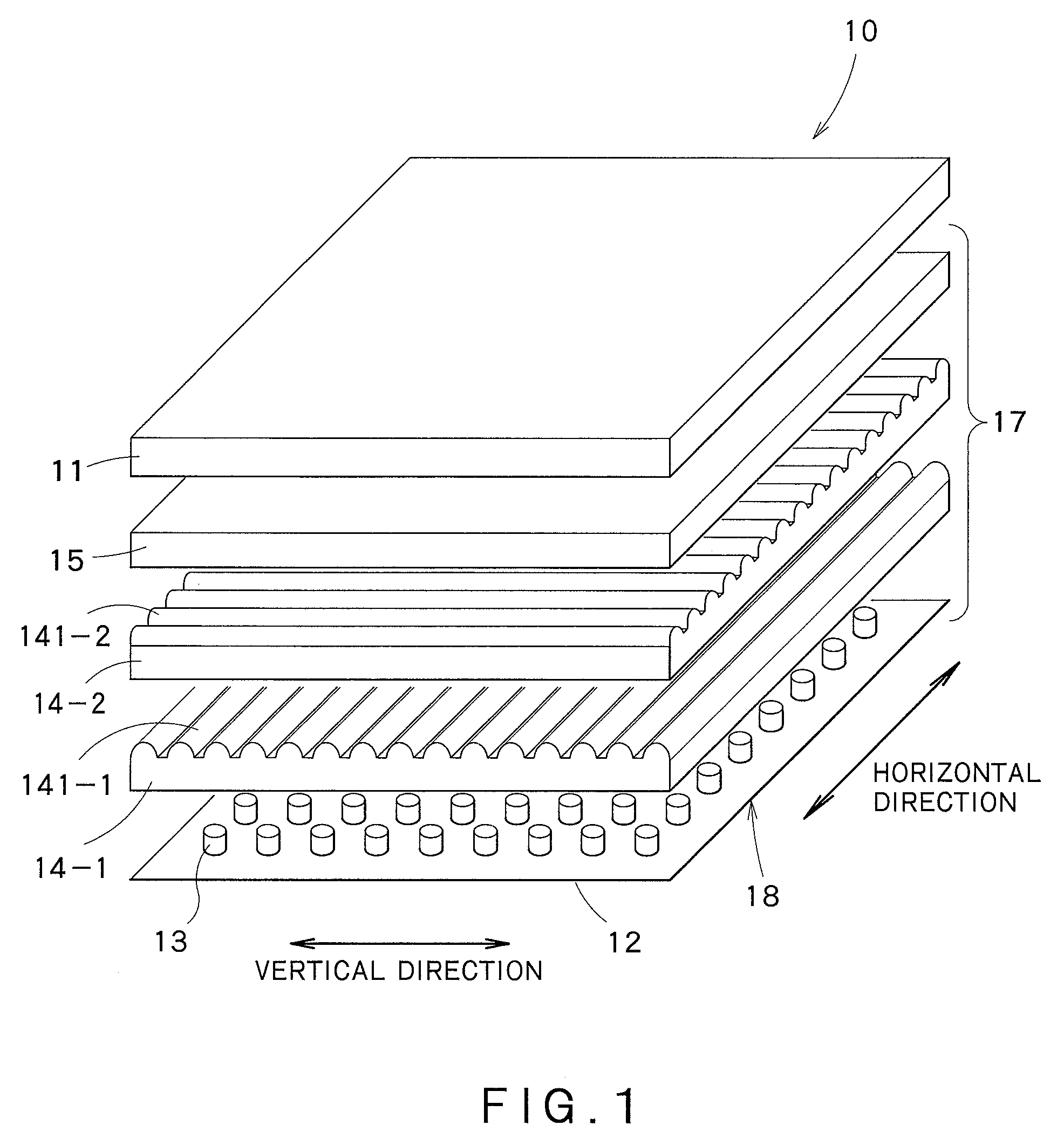
[0033]FIG. 1 is an exploded perspective view of a transmission-type display device including a surface light source device according to a first embodiment of the present invention. As shown in FIG. 1, the transmission type display device 10 comprises an LCD panel 11, a reflector 12, light-emitting sources 13, a lenticular lens sheet 14-1, a second lenticular lens sheet 14-2, and a reflective polarization sheet 15. The transmission-type liquid crystal display device 10 is a device that illuminates the LCD panel 11 from its rear to display image information produced on the LCD panel 11. A surface light source device 17 for illuminating the LCD panel 11 from its rear is formed by the reflector 12, the light-emitting sources 13, the lenticular lens sheet 14-1, the second lenticular lens sheet 14-2, and the reflective polarization sheet 15.

[0034]The LCD panel 11 is composed of liquid crystal display elements of so-called transmission type. The LCD panel 11 is 30 inches in size, and is so...

second embodiment

[0061]FIG. 5 is a view of light-emitting sources of a surface light source device according to a second embodiment of the present invention, when viewed from the observation side.

[0062]Although this embodiment differs from the first embodiment as to a light source unit 18′, the other structures of this embodiment are substantially the same as those of the first embodiment. The same parts as those of the first embodiment are indicated by the same reference numbers, and their detailed description is omitted.

[0063]The light source unit 18′ in this embodiment is composed of three types of light emitting sources of different luminescent colors, which are arranged in a two-dimensional direction in a predetermined regular order. The three types of light emitting sources are classified into blue-light emitting sources 13B for emitting blue light, green-light emitting sources 13G for emitting green light, and red-light emitting sources 13R for emitting red light. These light-emitting sources...


PUM


Abstract

A surface light source device including a light source unit having a plurality of light-emitting sources in a two-dimensional direction, and a lenticular lens sheet having a plurality of unit lenses, each of which is a part of a substantially elliptic cylinder, such that lens surfaces of the unit lenses face a light emergent side. There is a particular relationship between an interval at which the light-emitting sources are arranged in the same direction as an arrangement direction of the unit lenses, an interval between the light emitting sources and a rear surface of the lenticular lens sheet, a unit-lens end-portion angle, and the refractive index of the material of the lens sheet.

Description

FIELD OF THE INVENTION[0001]The present invention relates to a surface light source device that illuminates a liquid crystal display or the like.BACKGROUND ART[0002]A variety of surface light source devices that are used to illuminate a transmission type of liquid crystal displays or the like from their rear have been proposed and put into practical use. Such surface light source devices are broadly classified into the edge light type and the direct type. These types differ from each other in the mode of conversion of a non-surface light source to a surface light source.[0003]For example, a surface light source device of the direct type is so constructed that light is introduced from its rear by cold-cathode tubes arranged in parallel. The cold-cathode tubes and a transmission type of display element such as an LCD (Liquid Crystal Display) panel are properly spaced from each other. In this space, there are placed a diffusing sheet and a combination of two or more sheets capable of c...

Claims


Application Information

Patent Timeline
IPC IPC(8): F21V13/04F21V5/04
CPCG02B3/06G02B5/0215G02F2001/133607G02F1/133603G02B5/0284G02F1/133607
Inventor GOTO, MASAHIRO
Owner DAI NIPPON PRINTING CO LTD
Why Eureka
Try Eureka