Multi-level memory cell programming methods

a memory cell and programming method technology, applied in the field of nonvolatile memory devices, can solve the problems of slow programming speed and slow programming speed of memory cells, and achieve the effect of more rapid and efficient programming

Active Publication Date: 2009-08-13
MACRONIX INT CO LTD
View PDF3 Cites 4 Cited by
  • Summary
  • Abstract
  • Description
  • Claims
  • Application Information

AI Technical Summary

Benefits of technology

[0017]Advantageously, during programming to a higher threshold state the initial bias for lower threshold stat

Problems solved by technology

Problems with these methods include a slow programming speed since the bias voltages for the initial programming step must be conservatively selected so as to prevent programming the memory cell to an incorrect stat

Method used


Image

  • Multi-level memory cell programming methods
  • Multi-level memory cell programming methods
  • Multi-level memory cell programming methods

Examples


Embodiment Construction

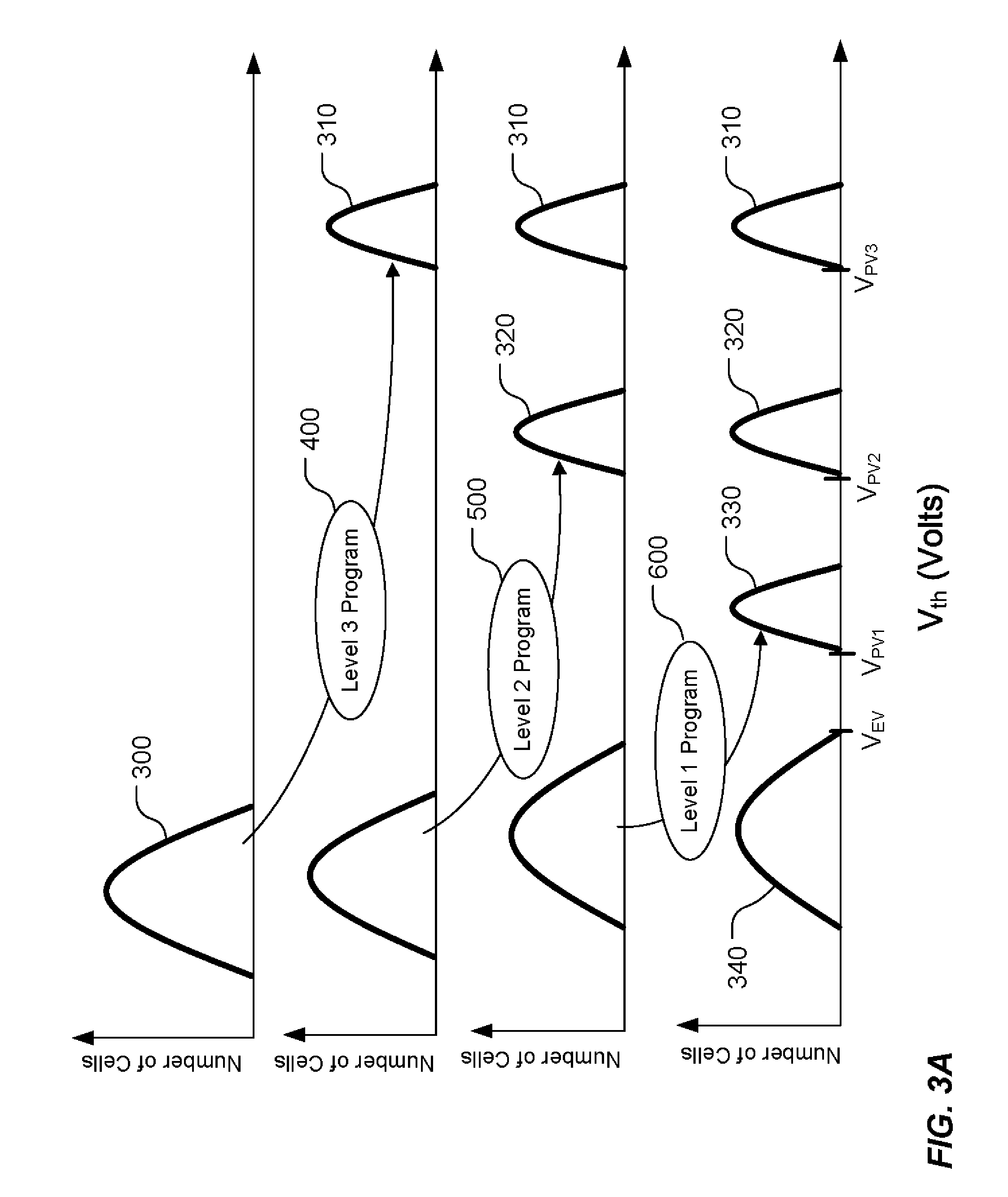
[0022]A detailed description is provided with reference to FIGS. 3A-3D.

[0023]FIGS. 3A-3D illustrate a method for programming multi-level memory cells. As described in more detail below, when a first set of memory cells are being programmed to a higher threshold state, the method determines the initial bias for use in programming memory cells to one or more of the lower threshold states. This is done by applying a succession of programming pulses to program the first set of memory cells to the higher threshold state and recording the bias voltage(s) of the most recent programming pulse when any of the first set of memory cells passes the program verify of a lower programmed state. The recorded bias voltage(s) can be stored in memory and used as the initial bias for programming of memory cells to the lower threshold state. Using the recorded bias voltages eliminates the need to select a conservative initial bias voltage, resulting in increased programming speed.

[0024]In the illustrate...


PUM


Abstract

A method for programming a plurality of multi-level memory cells described herein includes iteratively changing a bias voltage applied to a first memory cell to program the first memory cell to a first threshold state and detecting when the first cell reaches a predetermined threshold voltage. The bias voltage applied to the first memory cell upon reaching the predetermined threshold voltage is recorded. A second memory cell is programmed to a second threshold state by applying an initial bias voltage to the second memory cell which is function of the recorded bias voltage.

Description

BACKGROUND OF THE INVENTION[0001]1. Field of the Invention[0002]The present invention relates generally to non-volatile memory devices, and more particularly to methods for programming multi-level cells.[0003]2. Description of Related Art[0004]Non-volatile memory technology includes memory cells that store charge between the channel and gate of a transistor. The charge stored affects the threshold voltage level Vth of the transistor, and the threshold voltage level of the transistor due to the stored charge can be sensed to indicate data.[0005]One type of charge storage memory cell is known as a floating gate memory cell. In a floating gate memory cell, source and drain regions are separated by a semiconductor channel region, a tunnel dielectric is formed over the channel, a floating gate of conductive material such as polysilicon is formed over the tunnel dielectric, and an inter-poly dielectric is formed over the floating gate to isolate it from the word line or control gate of th...

Claims


Application Information

Patent Timeline
IPC IPC(8): G11C16/04G11C16/06
CPCG11C2211/5621G11C11/5628
Inventor CHANG, CHIN-HUNGHO, WEN-CHIAOCHANG, KUEN-LONGHUNG, CHUN-HSIUNG
Owner MACRONIX INT CO LTD
Why Eureka
Try Eureka