Optical head device for forming light spot on disc-shaped information medium

a technology of disc-shaped information and optical head device, which is applied in the direction of optical recording head, data recording, instruments, etc., can solve the problems of difficult to reduce the size and thickness the height of the optical head device has to be increased, etc., to achieve accurate positioning, and increase the height of the optical head devi

Active Publication Date: 2009-08-13
PANASONIC CORP
View PDF3 Cites 6 Cited by
  • Summary
  • Abstract
  • Description
  • Claims
  • Application Information

AI Technical Summary

Benefits of technology

[0025]In addition, with at least one luminous flux direction changing means provided offset in the configuration that has the plurality of luminous flux direction changing means, a compact thin optical head device that is able to prevent the collision of the objective lens with the luminous flux direction changing means without increasing the height of the optical head device can be provided.
[0026]Further, by including the second moving means pivotally moving the facing luminous flux direction changing means so that at least one of the plurality of luminous flux direction changing means opposes the corresponding objective lens in the configuration that has the plurality of luminous flux direction changing means, a compact thin optical head device that prevents the collision of the objective lens with the luminous flux direction changing means without increasing the height of the optical head device can be provided.
[0027]Still Further, by including the plurality of objective lenses arranged in the tangential direction or the radial direction and the second moving means moving the luminous flux direction changing means in the tangential direction or the radial direction, an optical head device that is compact and thin in the radial direction or the tangential direction can be provided.
[0028]In addition, by including the second moving means having the lock mechanism, an optical head device that is able to accurately fix the position of the luminous flux direction changing means and resistant to vibrations can be provided.
[0029]Further, by including the second moving means moving the luminous flux direction changing means stepwise or steplessly, the luminous flux direction changing means can be placed at an optimal position, and a compact high-performance optical head device that is able to reduce the size of the eclipse of the luminous flux due to the luminous flux direction changing means can be provided.
[0030]In addition, a disc recording apparatus, a disc reproducing apparatus and a disc recording and reproducing apparatus, which produce effects similar to those of the optical head device, can be provided.

Problems solved by technology

Accordingly, there has been such a problem that the height H of the optical head device has needed to be increased in order to avoid the collision, and it has been difficult to reduce the size and thickness of the optical head device.

Method used


Image

  • Optical head device for forming light spot on disc-shaped information medium
  • Optical head device for forming light spot on disc-shaped information medium
  • Optical head device for forming light spot on disc-shaped information medium

Examples


first preferred embodiment

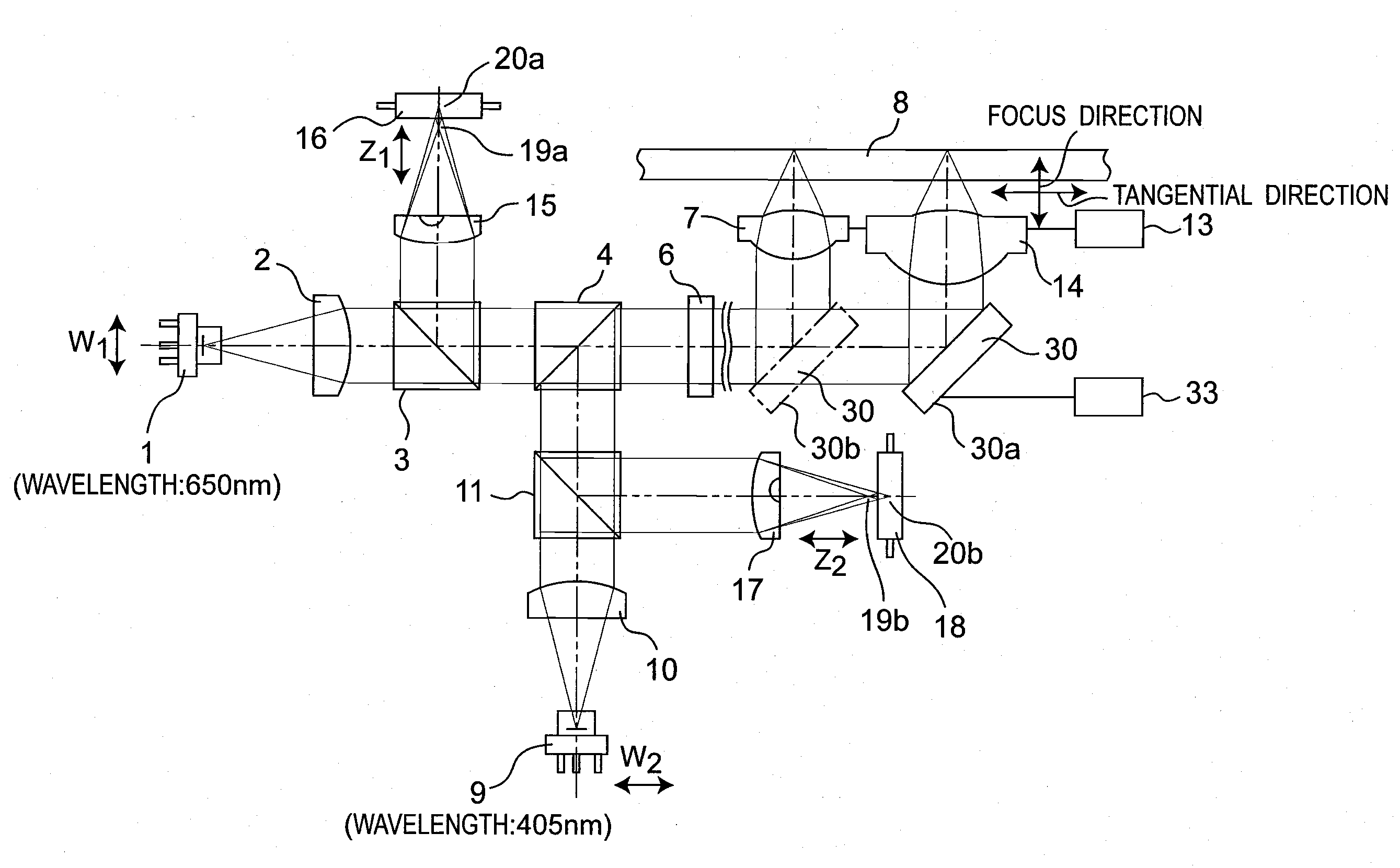
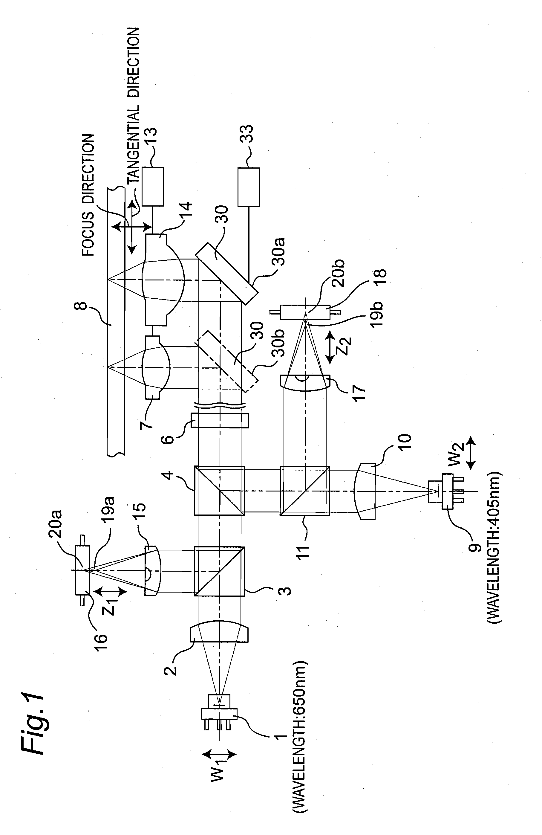
[0117]FIG. 1 is a schematic view of an optical system showing an optical head device according to the first preferred embodiment. The optical head device according to the present preferred embodiment is mounted in a disc recording and reproducing apparatus that records an information signal on a disc-shaped information recording medium 8 of, for example, a DVD (Digital Versatile Disc), BD (Blue-ray Disc) or the like by means of a luminous flux and reproduces an information signal from the information recording medium 8 by means of a luminous flux. Referring to FIG. 1, the optical head device of the present preferred embodiment is constituted of semiconductor lasers 1 and 9, collimating lenses 2 and 10, polarization beam splitters 3 and 11, a wavelength-selecting prism 4, a quarter-wave plate 6, a upward-reflecting mirror 30, an objective lens 7 for a wavelength of 650 nm, an objective lens 14 for a wavelength of 405 nm, an objective lens actuator 13 that moves the objective lenses 7...

second preferred embodiment

[0141]FIG. 13 is a schematic view of an optical system showing an essential part of an optical head device according to the second preferred embodiment in a case where laser light having a wavelength of 405 nm is used. Referring to FIG. 13, the optical head device of the present preferred embodiment differs from the optical head device of the first preferred embodiment shown in FIGS. 1 to 10 in that the objective lenses 7 and 14 are arranged in the radial direction instead that they are arranged in the tangential direction and a upward-reflecting mirror 30A, a retention member 31A, a driving force 32A and a moving mechanism 33A are provided in place of the upward-reflecting mirror 30, the retention member 31, the driving force 32 and the moving mechanism 33. The optical head device of the present preferred embodiment is similar to the optical head device of the first preferred embodiment in the other points, and no detailed description is provided for the components denoted by the s...

third preferred embodiment

[0146]FIG. 16 is a schematic view of an optical system showing an essential part in a case where laser light having a wavelength of 650 nm is used in an optical head device according to the third preferred embodiment. Referring to FIG. 16, the optical head device of the present preferred embodiment differs from the optical head device of the first preferred embodiment shown in FIGS. 1 to 10 in that a prism 45 is provided in place of the upward-reflecting mirror 30. The optical head device of the present preferred embodiment is similar to the optical head device of the first preferred embodiment in the other points, and no detailed description is provided for the components denoted by the same reference numerals.

[0147]FIG. 24 is a schematic view of an optical system showing an essential part of an optical head device in a case where two prisms 45A and 45B are arranged side by side in the tangential direction. When a plurality of upward-reflecting mirrors are employed, transmitted lig...


PUM

PropertyMeasurementUnit
luminous fluxaaaaaaaaaa
surface reflectanceaaaaaaaaaa
densitiesaaaaaaaaaa

Abstract

An optical head device has at least one upward-reflecting mirror, objective lenses, an objective lens actuator, and a moving mechanism. The upward-reflecting mirror receives an incident luminous flux having a wavelength emitted from a semiconductor, and changes its direction. The objective lenses having mutually different numerical apertures condenses the luminous flux whose direction has been changed by the upward-reflecting mirror to radiate a condensed luminous flux onto an information recording medium. The objective lens actuator moves the objective lenses in the focus direction of the information recording medium so that the luminous flux incident on the information recording medium becomes in a focused state. The moving mechanism moves the upward-reflecting mirror so that the luminous flux is incident on the information recording medium via any one of the objective lenses.

Description

TECHNICAL FIELD[0001]The present invention relates to an optical head device for forming a light spot on a disc-shaped information recording medium for recording information on the information recording medium or for reproducing information from the information recording medium and to a disc recording apparatus, a disc reproducing apparatus and a disc recording and reproducing apparatus each provided with the same optical device.BACKGROUND ART[0002]In recent years, disc recording and reproducing apparatuses have been compatible with a variety of recording media including those for DVD (Digital Versatile Disc), BD (Blue-ray Disc), CD (Compact Disc), personal computers and so on and have the applications thereof diversified year by year. In addition, in accordance with demands for increasing the densities of the recording media, the disc recording and reproducing apparatuses are demanded to have high performances and high recording densities. In particular, disc recording and reproduc...

Claims


Application Information

Patent Timeline
Patent Type & Authority Applications(United States)
IPC IPC(8): G11B7/135
CPCG11B7/1362G11B2007/0006G11B7/1374
Inventor NAKATA, HIDEKIAIKOH, HIDEKI
Owner PANASONIC CORP
Why Eureka
Try Eureka