Air conditioning system for vehicle
- Summary
- Abstract
- Description
- Claims
- Application Information
AI Technical Summary
Benefits of technology
Problems solved by technology
Method used
Image


Examples
first embodiment
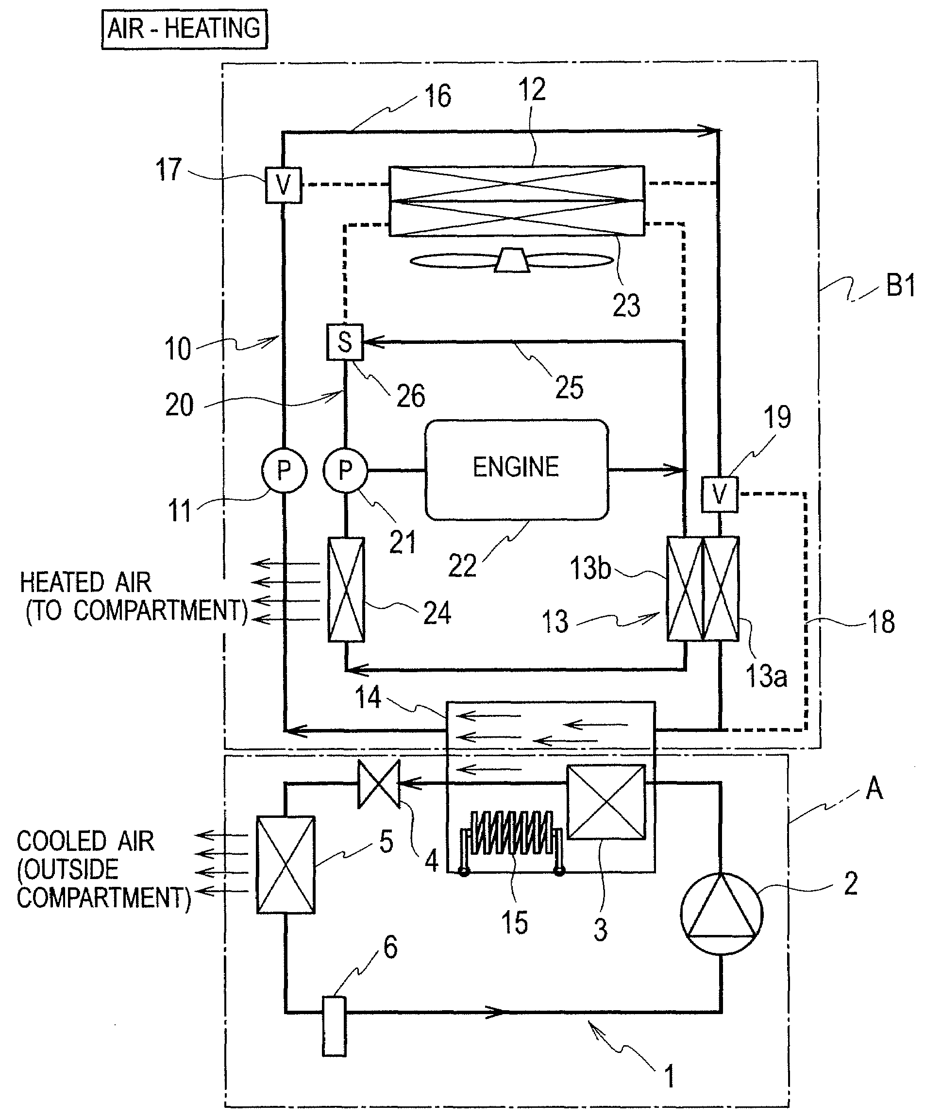
[0052]an air conditioning system for a vehicle according to the present invention will be explained with reference to FIGS. 1 to 3. As shown in FIG. 1, the air conditioning system is combined of a heat-pump type cooling unit A and an air-heating circulation unit B1.
[0053]The heat-pump type cooling unit A includes a first circulation path 1. The first circulation path 1 is filled with first refrigerant (CO2). A compressor 2, a water-cooled condenser 3, an expansion valve (expansion unit) 4, an evaporator 5 and a accumulator 6 are provided on the first circulation path 1 in this order.
[0054]The compressor 2 inhales the relatively low-temperature and pressure first refrigerant and discharges the high-temperature and pressure first refrigerant after compressing it.
[0055]The water-cooled condenser 3 is arranged within an after-mentioned unit container 14 on the second circulation path 10. The first refrigerant output from the compressor 2 is cooled by the second refrigerant. Specifically...
second embodiment
[0092]Since other configurations in the present embodiment is equal or similar to those in the second embodiment, redundant explanations will be omitted by allocating identical numerals to the identical or similar configurations.
[0093]As shown in FIG. 8, operations during air-heating are almost the same as the second embodiment. As shown in FIG. 9, operations during air-cooling are almost the same as the second embodiment.
[0094]In the present embodiment, the heat-pump type cooling unit A can be simplified in the air-conditioning system that achieves air-heating and air-cooling by using the waste heat of the heat-pump type cooling unit A and the engine 22 as similarly as the second embodiment.
[0095]In the present embodiment, the internal heat exchanger 13A includes the heat exchanger 13c through which the third refrigerant flows and the heat exchanger 13c is provided on (within) the flowing path of the second refrigerant, more specifically within the unit container 14. Therefore, thi...
third embodiment
[0098]Specifically, a branching path 31, a fifth flow-path changeover valve (fifth flow-path changeover unit) 32 and a third pump 33 are further provided on the third circulation path 20. The branching path 31 divides the third circulation path 20 into a circulation system of the engine 22 and another circulation system of the heater core 24. The fifth flow-path changeover valve 32 changes over whether or not to flow the third refrigerant to the branching path 31. The third pump 33 is provided for the branching path 31. The branching path 31 is interposed between the fourth flow-path changeover valve 30 and the fifth flow-path changeover valve 32. It can be controlled by changing over the fourth flow-path changeover valve 30 and the fifth flow-path changeover valve 32 whether or not to flow the third refrigerant to the branching path 31. Although the fourth flow-path changeover valve 30 is used to close or open the flowing path in the above third embodiment, it is used to change ove...
PUM
 Abstract
Description
Claims
Application Information