Supercharge Your Innovation With Domain-Expert AI Agents!

Check Scanning Apparatus and Methods

Inactive Publication Date: 2009-08-20
DIGITAL CHECK CORP
View PDF7 Cites 17 Cited by
  • Summary
  • Abstract
  • Description
  • Claims
  • Application Information

AI Technical Summary

Benefits of technology

[0016]The check scanner may further include a printer disposed along the path for printing information on the check when the check passes the printer in the forward direction and / or when the check passes the printer in the reverse direction. A pair of contact image sensors is disposed on opposite sides of the path, for scanning both sides of the check when the check passes the pair of contact image sensors in the forward direction and again when the check passes the contact image sensors in the reverse direction to provide two distinct scans of each side of the check. Preferably, the pair of contact image sensors has a resolution of at least 300 dots per inch to provide a higher resolution grey scale image of both sides of the check when the check is scanned in one direction and also the ability to provide a color image of both sides of the check when the check is scanned in the opposite direction. The check scanner includes a magnetic ink character recognition (MICR) reader disposed along the path for reading information printed on the check when the check passes the magnetic ink character recognition reader in the forward direction and again when the check passes the magnetic ink character recognition reader in the reverse direction.
[0027]Another embodiment of the present invention is concerned with a check scanner including a base plate, a pair of spaced-apart walls attached to said base plate, the spaced-apart walls defining a path between the walls for routing of said check in the check scanner, a pair of contact image sensor heads attached to the walls for obtaining images of the check, a magnetic ink character recognition reader attached to one of the walls to read information from the face of the check, and a print head attached to one of the walls for printing information on the check, whereby the pair of spaced apart walls may be easily assembled onto the base with the pair of contact image sensor heads, the magnetic ink character recognition reader and the printer head preassembled onto the pair of spaced-apart walls.

Problems solved by technology

Prior art check scanners also suffer from relatively high manufacturing and assembly costs.
For example, many of the internal components, such as the CIS scanning heads, the MICR reader, the printer head assembly, the transport rollers, sensors and the like, are typically separately mounted onto the base plate of the check scanner, which is time consuming and costly due to the positional accuracy requirements of these components to the associated 90 degree scanning plane.

Method used


Image

  • Check Scanning Apparatus and Methods
  • Check Scanning Apparatus and Methods
  • Check Scanning Apparatus and Methods

Examples


Embodiment Construction

[0044]It will be understood that the present invention may be embodied in other specific forms without departing from the spirit thereof. The present examples and embodiments, therefore, are to be considered in all respects as illustrative and not restrictive, and the invention is not to be limited to the details presented herein.

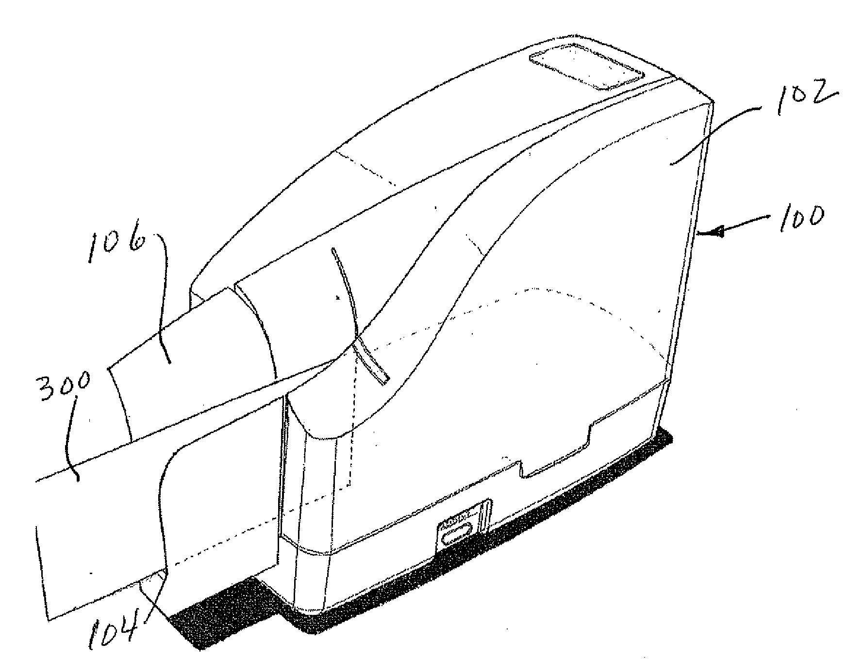
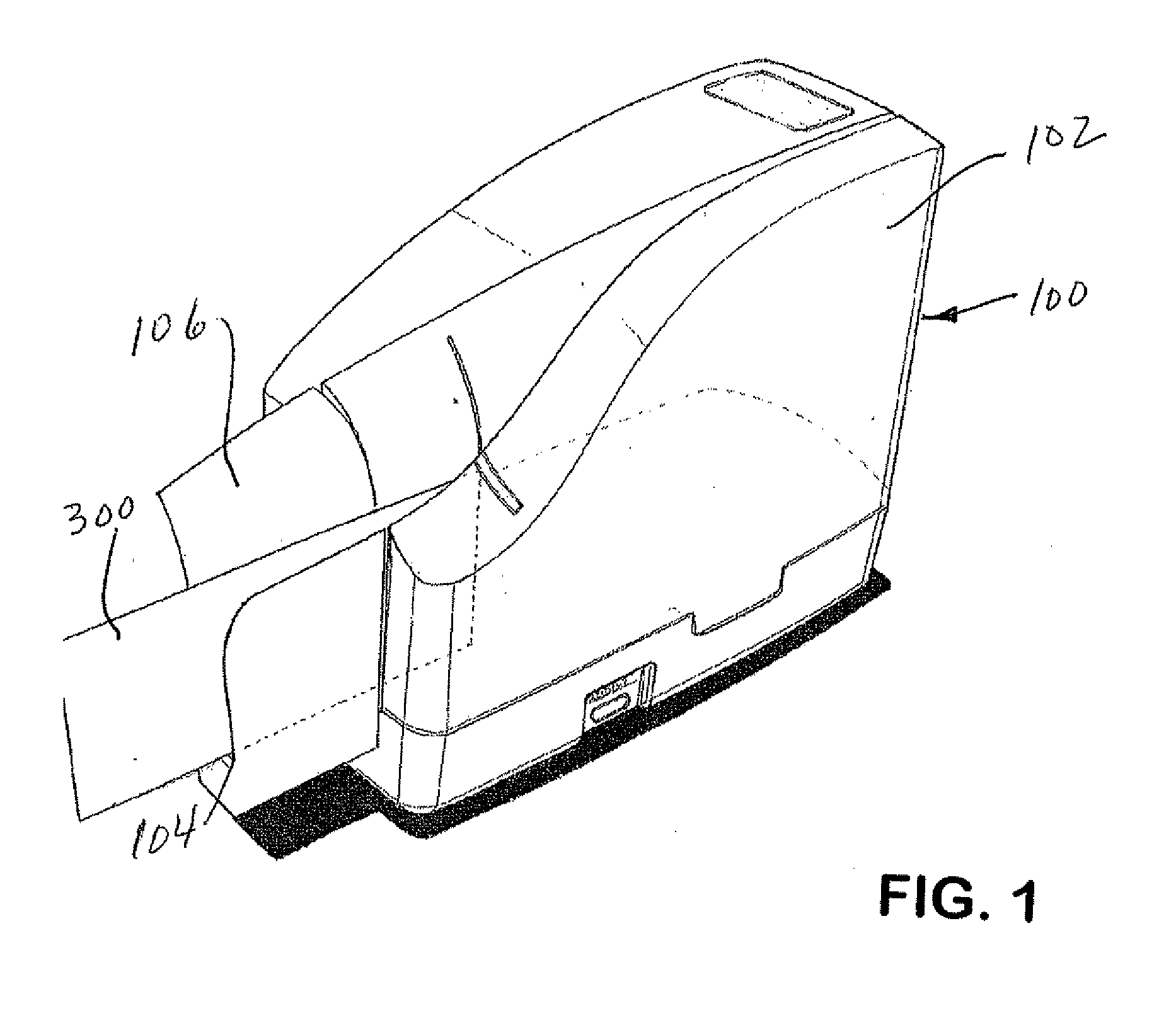
[0045]FIG. 1 illustrates a check scanning device 100. Check scanning device 100 may alternatively be described herein as a check scanner, or the like. Check scanner 100 is particularly suited for scanning and imprinting checks, such as check 300. However, the various aspects of the present invention may be utilized in the scanning or processing of other types of documents. Scanner 100 preferably has a removable top cover 102. For example, cover 102 can be removed to service or inspect the internal components of scanner 100, such as to replace an ink cartridge or the like. Checks to be scanned are inserted into a generally vertically disposed slot 104. Slot ...


PUM


Abstract

A check scanner endorses or cancels a check with a print head when the check is driven in the forward direction, and franks, endorses or prints again when the check is driven in the reverse direction. Two separate images of each side of the check are generated for digital comparison and verification purposes by scans with contact image sensors (CIS), with one image from scanning in the forward direction and another image from scanning in the reverse direction. A high resolution image may be obtained by CIS scanning when the check is driven in the forward direction and an even higher resolution image may be obtained by CIS scanning when the check is driven in the reverse direction. Alternately, a grey scale image may be obtained by CIS scanning when the check is driven in the forward direction, and a color image may be obtained by CIS scanning when the check is driven in the reverse direction. After scanning, the check is returned back to the original point of entry.

Description

FIELD OF THE INVENTION[0001]The present invention relates generally to improved methods and apparatus for scanning of checks.BACKGROUND OF THE INVENTION[0002]Check scanners are utilized in most banks and also in corporate offices, and many retail and service establishments. Traditional check scanners utilize a horseshoe or U-shaped passage for scanning of a check with a first input end into which the check is inserted. The check is then moved in a single direction through the passage by a drive mechanism. When the check reaches the second output end of the passage, it is typically collected in an output tray.[0003]Positioned along the passage is a magnetic head for reading the special characters imprinted with magnetic ink, usually along a bottom edge of the check. This process is known in the art as magnetic ink character recognition, or by the acronym MICR. The MICR reading head is typically small since it only needs to read the bottom portion of the check which has the magnetic i...

Claims


Application Information

Patent Timeline
IPC IPC(8): G06F17/00
CPCG06K9/186H04N1/00572H04N1/00594H04N1/00602H04N1/00612H04N2201/33314H04N1/0402H04N1/0408H04N1/0455H04N1/203H04N1/2034H04N1/00615G06V30/2253
Inventor EMBURY, GLENN R.BARBONI, PHILIP G.
Owner DIGITAL CHECK CORP
Features
  • R&D
  • Intellectual Property
  • Life Sciences
  • Materials
  • Tech Scout
  • Unparalleled Data Quality
  • Higher Quality Content
  • 60% Fewer Hallucinations
Learn More