
Self-cleaning assembly employing a gap filler for a guidance or runway rail on the ground

a gap filler and self-cleaning technology, applied in rails, railway tracks, ways, etc., can solve the problems of local blockage of gap, damage to rollers or wheels, derailment, etc., and achieve the effect of ensuring the reliability and safety of guiding

Inactive Publication Date: 2009-08-20
LOHR IND
View PDF8 Cites 4 Cited by
  • Summary
  • Abstract
  • Description
  • Claims
  • Application Information

AI Technical Summary

Benefits of technology

[0012]The urban integration of ground-level guiding means by rails flush with the surface has specific advantages and, thanks to the invention, ensures the reliability and safety of guiding and rolling even in the locations most exposed to all kinds of debris and to bad weather.
[0013]The gap lining material has compressibility properties that enable it to ensure the cleaning of objects during or after the passage of the roller(s) or wheel(s), or their obliteration or pressing down into the material during the passage.

Problems solved by technology

Owing to its exposure to bad weather and to the environment, it often happens that the gap is locally blocked by an accumulation of plant matter, ice, snow, pebbles or other foreign bodies or objects that can obstruct the flange(s) during the passage of the guide roller(s) or railway wheels.
Such obstacles can lead to severe problems, such as damage to the rollers or wheels or, more seriously, to their derailment.
However, such cleaning is time-consuming and expensive, and cannot be carried out during operation of the transport network and in particular that part of it using the rail concerned.
Besides, even regular cleaning does not ensure the total cleanliness of gaps constantly exposed to bad weather, discarded garbage and attempted vandalism.
Such protection, however, is quite useless against debris and small objects that may be present in one or other of the channels along the rail, which potentially endanger the guiding function and the vehicle's rollers or wheels.

Method used


Image

  • Self-cleaning assembly employing a gap filler for a guidance or runway rail on the ground
  • Self-cleaning assembly employing a gap filler for a guidance or runway rail on the ground
  • Self-cleaning assembly employing a gap filler for a guidance or runway rail on the ground

Examples


Embodiment Construction

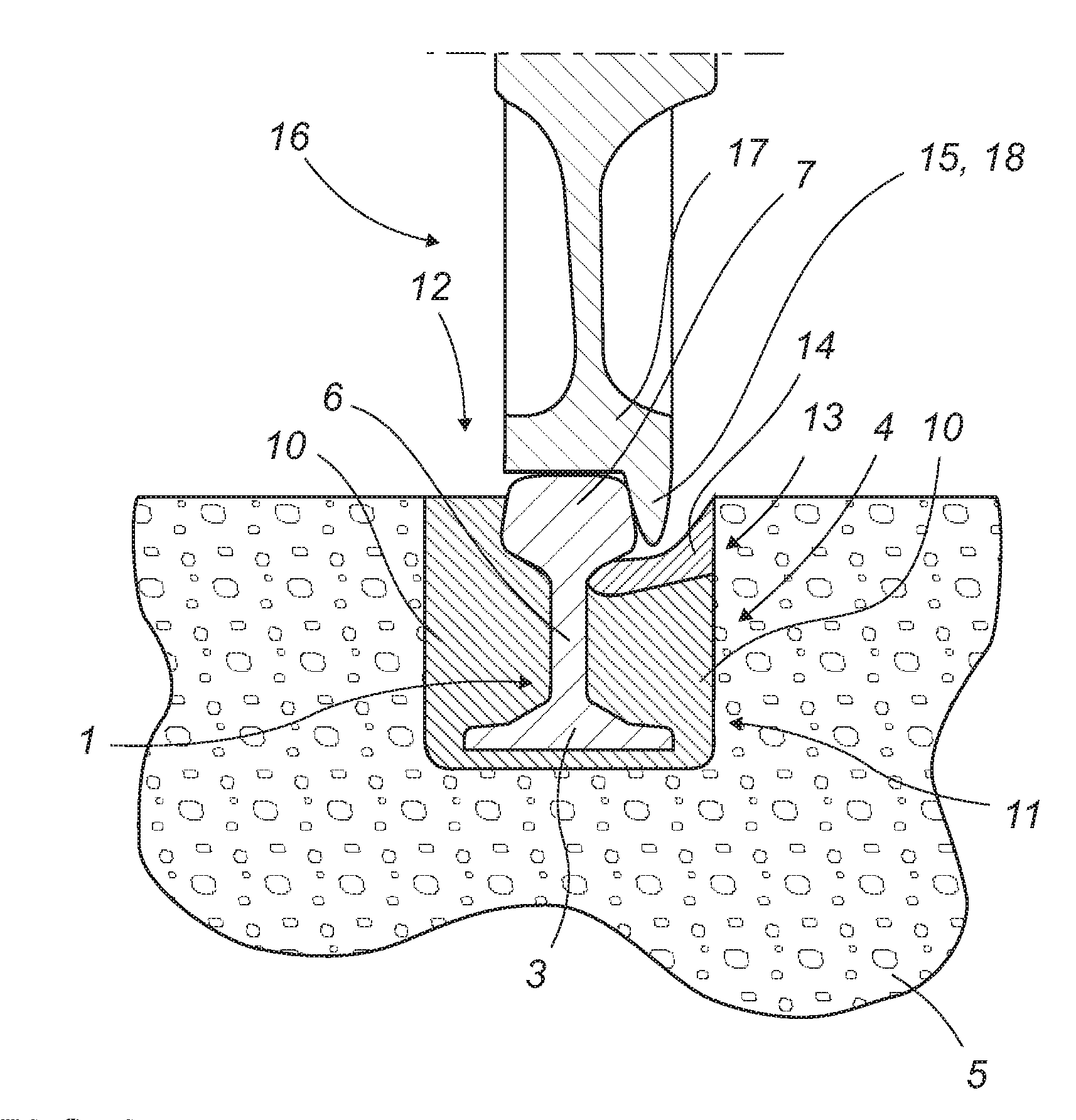
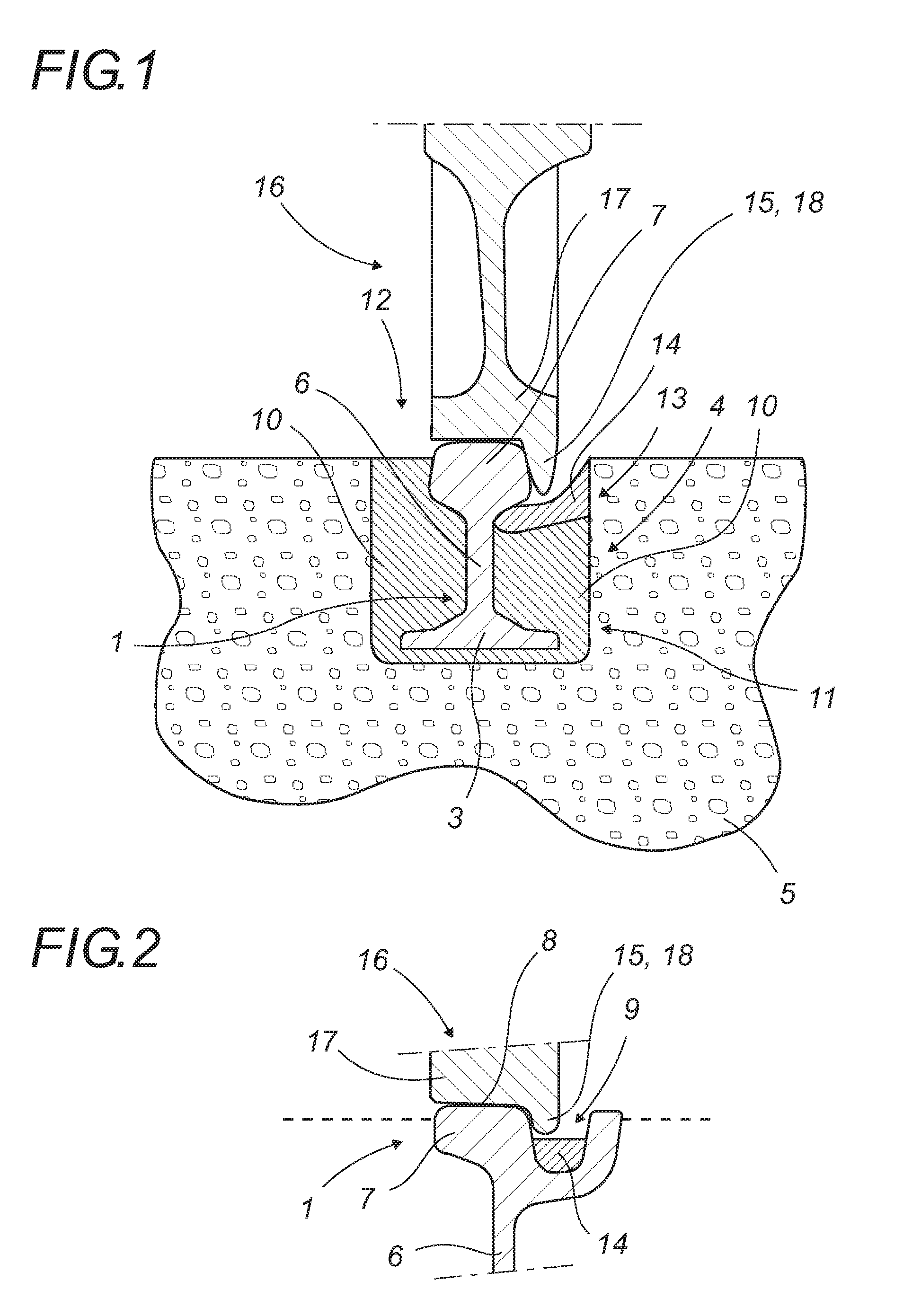
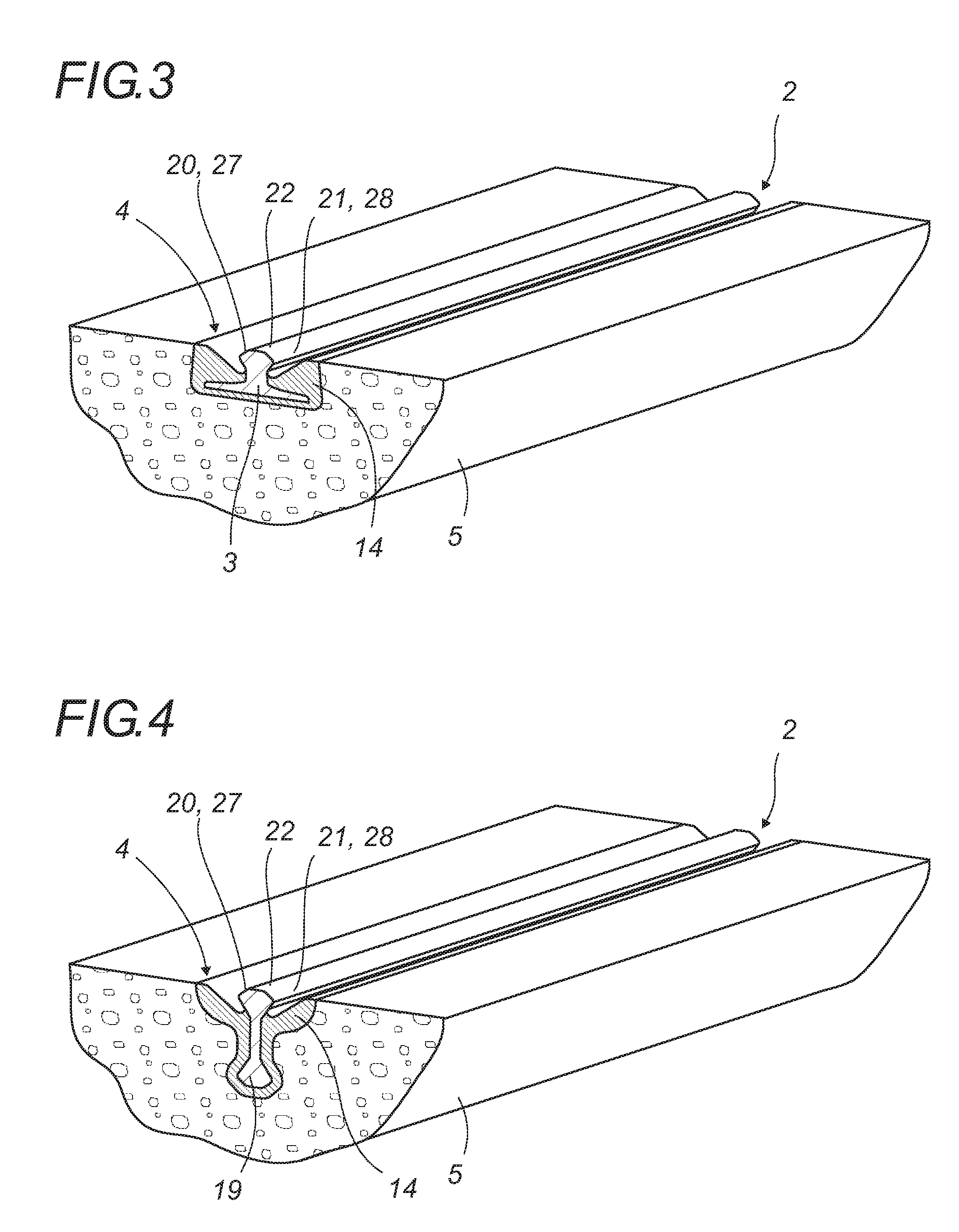
[0029]The gap lining for a guide-rail or rolling rail according to the present invention will now be described in detail with reference to FIGS. 1 to 12. Equivalent elements in the various figures will be given the same index numbers.

[0030]The gap lining is applied to guide-rails for flanged rollers arranged vertically or inclined, but also for railway wheels, i.e. wheels with a flange that roll on a rail in the vertical or inclined position, whether alone or in pairs.

[0031]FIGS. 1 and 2 aim to illustrate the general nature of the application of the present invention, by showing the case of a railway rolling rail with a classical profile and then one with a grooved profile.

[0032]As shown, the invention relates as much to a ground rail 1 for the rolling of a railway vehicle as to a ground-level guide-rail 2.

[0033]The rails 1 and 2 to which the invention relates are ones of the type comprising in particular a supporting base or foot 3 positioned below ground level and of the type that...


PUM


Abstract

A self-cleaning assembly employing a gap filler for a rail on the ground which guides or in which there runs rollers or wheels with lugs housed in a groove so as to lie flush with or protrude only slightly from the ground and which has a gap on the side of the rail corresponding to the passage of the lug. A filling substance is placed in the gap outside of the dynamic footprint of the lug and at least partially lines the gap, at least partially filling it. The filling material has properties of compressibility and is positioned in such a way that under all normal conditions of use or normal environmental conditions, the gap remains filled outside of the dynamic footprint of the lug.

Description

[0001]National stage of PCT / FR2007 / 001043 filed Jan. 22, 2007 which claims priority from French Application 0606199 filed Jul. 7, 2006FIELD OF INVENTION[0002]The invention relates to a gap lining for a rail used for guiding or rolling a railway or urban public transport vehicle by means of at least one flanged roller or railway wheel.[0003]The top surface of the rail is generally flush with the ground or slightly above ground level.[0004]In a particular application the invention concerns a gap lining for a guide-rail embedded in the ground with edges that form rolling tracks for an assembly that guides a vehicle on tires by means of one inclined roller or a pair of the same.[0005]Classically, for guiding or rolling by or with one or more flanged roller(s) there must be a free space between the flange, the adjacent edge of the recess holding the rail and the rail fixture. This space is known as the “gap”, and the said gap or gaps form(s) one or two channel(s) on either side all along...

Claims


Application Information

Patent Timeline
IPC IPC(8): E01B3/00
CPCE01B25/28
Inventor ANDRE, JEAN-LUC
Owner LOHR IND
Learn More