
Power supply circuit

a power supply circuit and circuit technology, applied in constant-current supply dc circuits, static indicating devices, instruments, etc., can solve problems such as the inability of known voltage step-up/down circuits to meet, and achieve the effect of reducing current consumption

Inactive Publication Date: 2009-08-20
RENESAS ELECTRONICS CORP
View PDF8 Cites 8 Cited by
  • Summary
  • Abstract
  • Description
  • Claims
  • Application Information

AI Technical Summary

Benefits of technology

[0009]According to the present invention, in the power supply circuit that generates a desired voltage by voltage multiplication, it is possible to satisfy both a demand to reduce current consumption and a demand to enable operation with a low power voltage at the same time.

Problems solved by technology

However, such known voltage step-up / down circuits cannot satisfy both a demand to reduce current consumption and a demand to enable operation with a low power voltage at the same time.
The aforementioned problem is generally applied to any circuits, which obtain a desired voltage by voltage multiplication, other than that for the liquid crystal driver.

Method used


Image

  • Power supply circuit
  • Power supply circuit
  • Power supply circuit

Examples


Embodiment Construction

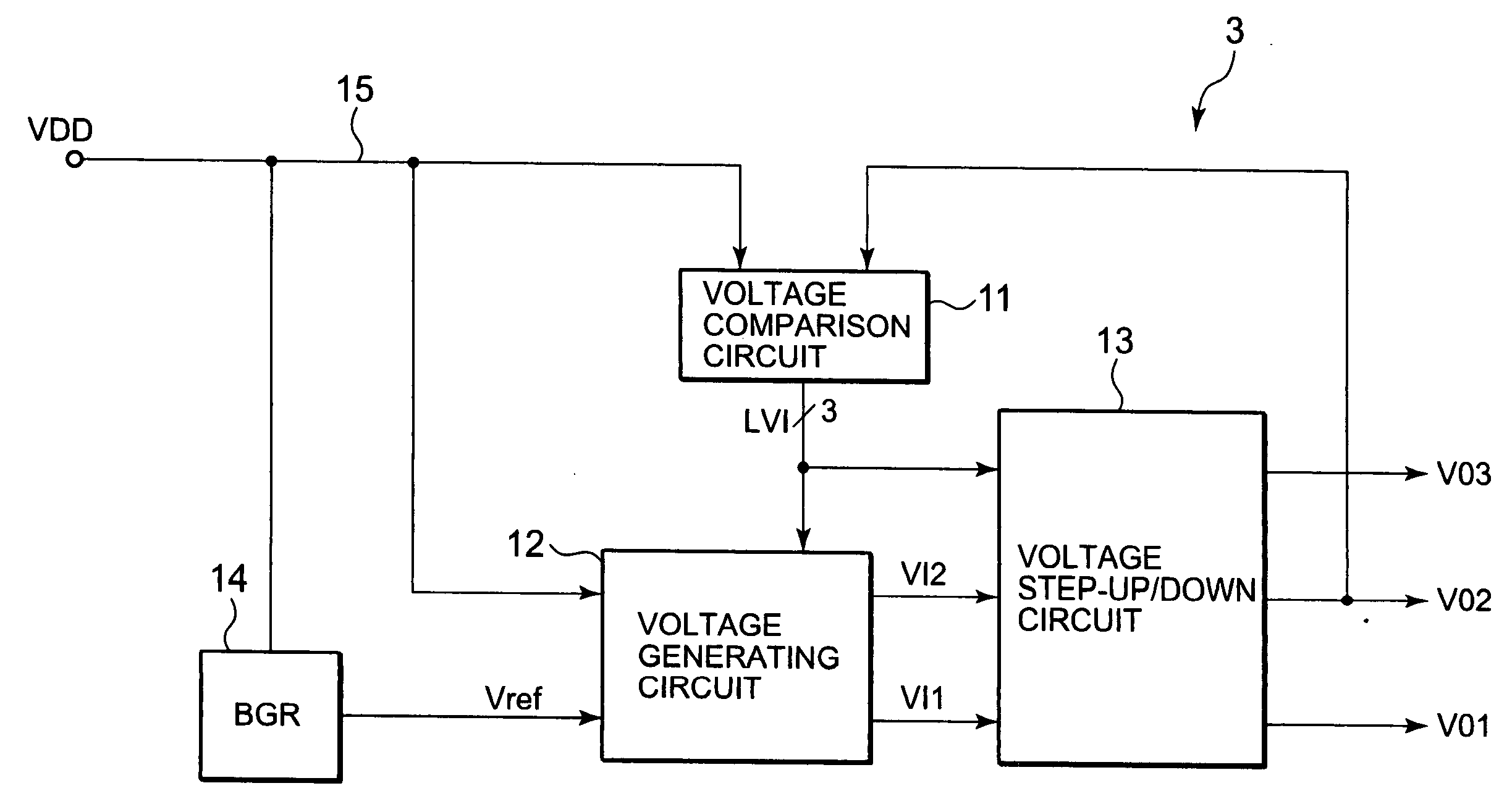
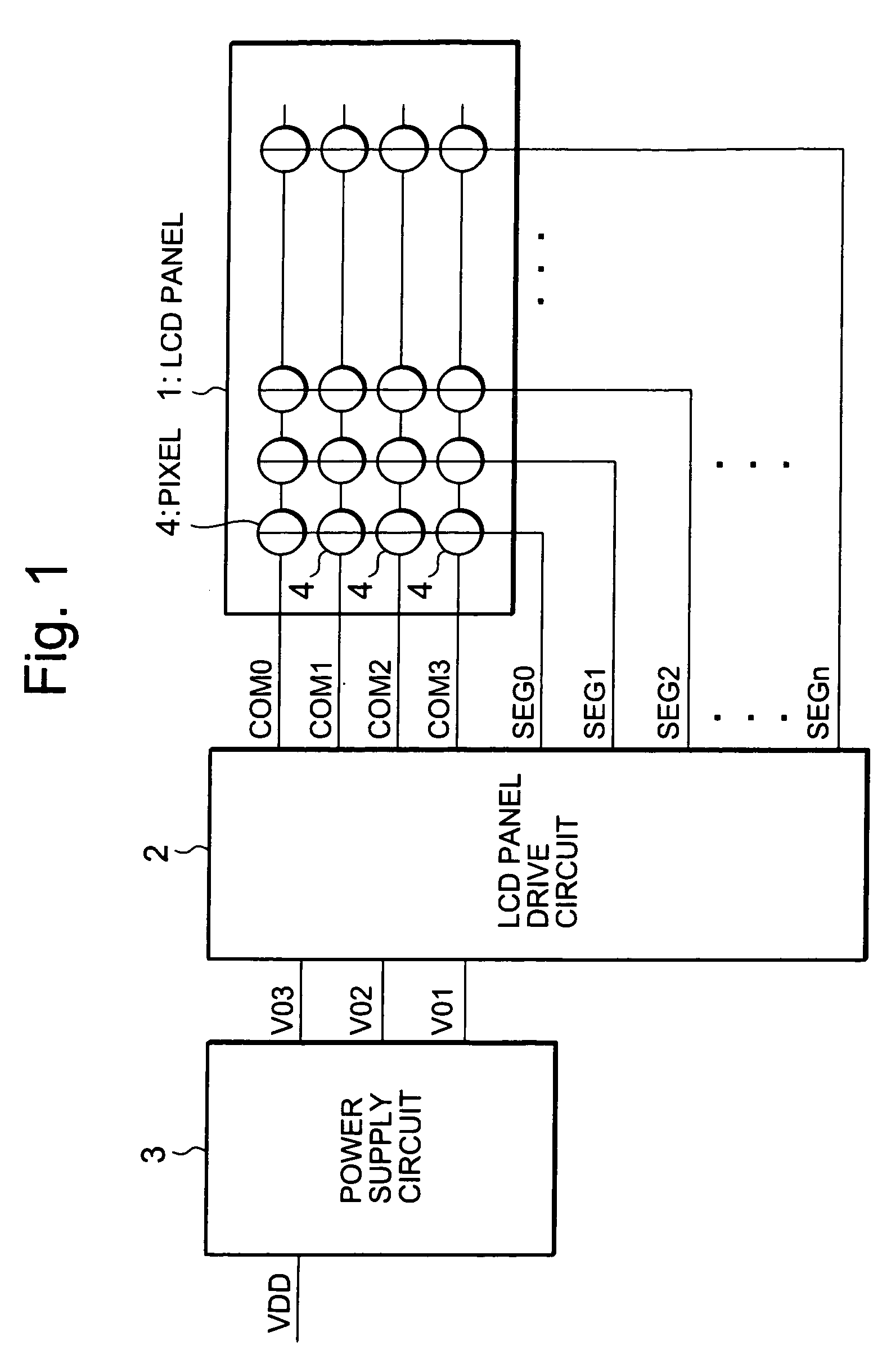
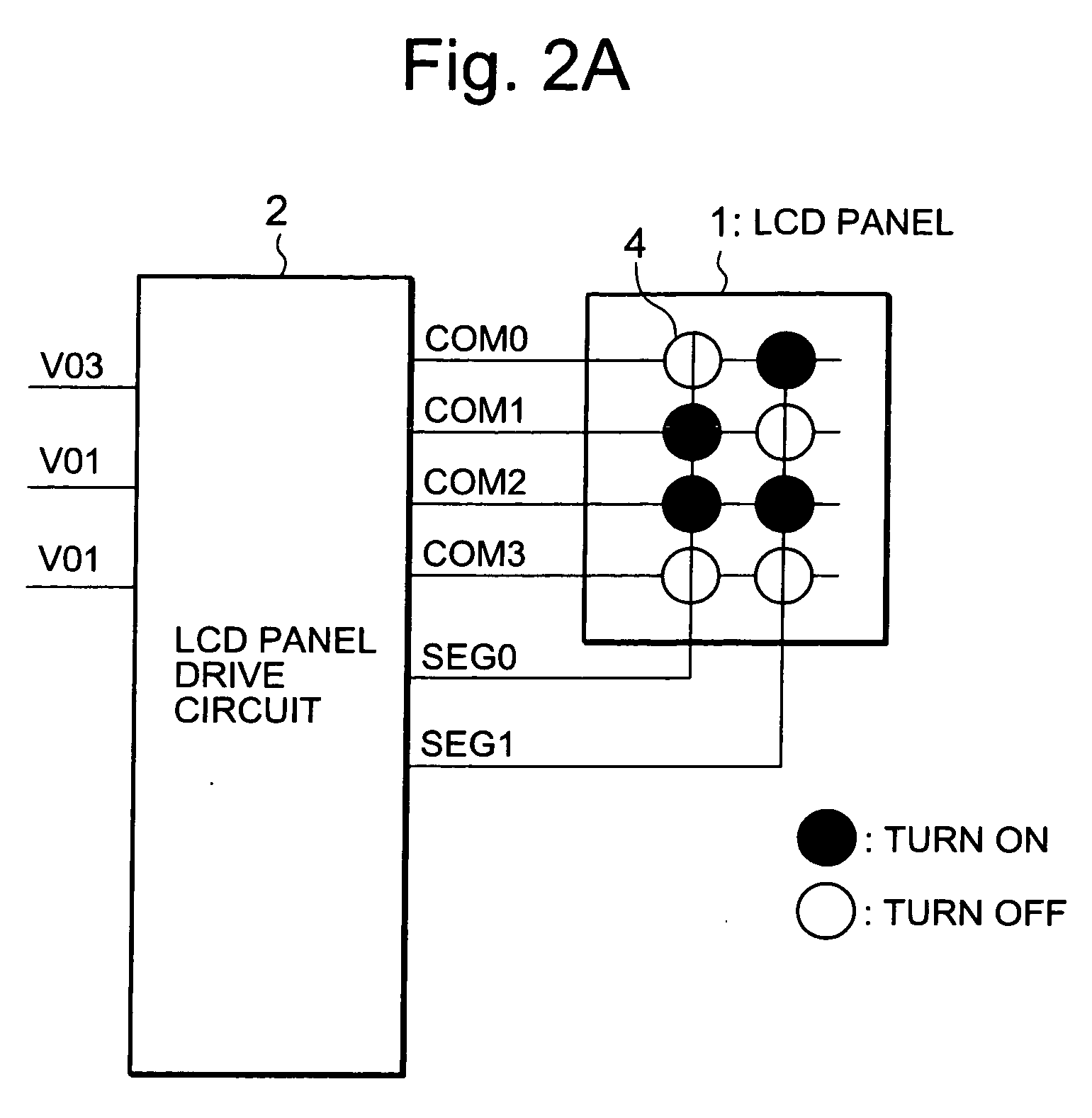
[0028]FIG. 1 is a block diagram illustrating a configuration of a liquid crystal display device 10 to which a power supply circuit of one embodiment of the present invention is applied. The liquid crystal display device 10 includes a LCD panel 1, a LCD panel drive circuit 2 and a power supply circuit 3. The LCD panel 1 is provided with common electrodes COM0 to COMm and segment electrodes SEG0 to SEGn, and pixels 4 are provided at positions where they cross one another. The LCD panel drive circuit 2 drives the common electrodes COM0 to COMm and the segment electrodes SEG0 to SEGn. The power supply circuit 3 generates voltages VO1 to VO3 from a power voltage VDD, and supplies the voltages VO1 to VO3 to the LCD panel drive circuit 2. Herein, the voltages VO1 to VO3 are generated so as to establish the following relationships, where Va* is a predetermined voltage:

VO1=Va*,  (1a)

VO2=2×Va*(=2×VO1), and  (1b)

VO3=3×Va*(=3×VO1)  (1c)

The LCD panel drive circuit 2 drives the common electrodes ...


PUM


Abstract

Provided is a power supply circuit generating a desired voltage by voltage multiplication, and satisfying both a demand to reduce current consumption and a demand to enable operation with a low power voltage at the same time. A power supply circuit of the present invention includes: a voltage generating circuit for generating internal voltages VI1 and VI2 from a power supply voltage VDD; a voltage step-up / down circuit for generating voltages VO1 to VO3 each having a different level by multiplying the internal voltages VI1 and VI12; and a voltage comparison circuit for comparing the voltage VO2 with the power supply voltage VDD. The voltage generating circuit is configured to select one of the internal voltages VI1 and VI2 according to an output of the voltage comparison circuit. Additionally, a voltage multiplication rate of the voltage multiplication circuit is switched according to the output of the voltage comparison circuit.

Description

BACKGROUND OF THE INVENTION[0001]1. Field of the Invention[0002]The present invention relates to a power supply circuit, and particularly relates to a power supply circuit that generates a desired output voltage by voltage multiplication.[0003]2. Description of the Related Art[0004]Within a semiconductor integrated circuit, there has been widely used a voltage step-up / down circuit that performs voltage multiplication of a power supply voltage to generate a desired voltage. For example, in a liquid crystal driver that drives a LCD (Liquid Crystal Display) panel, the voltage step-up / down circuit performs voltage multiplication of an internal reference power supply voltage Vci to thereby generate a drive voltage of the liquid crystal display panel. To be specific, Japanese Patent Application Publication No. 2004-4609 discloses a technique in which a capacitor and a switch quadruple an internal reference power supply voltage Vci to generate a voltage V0; and then the voltage V0 is volta...

Claims


Application Information

Patent Timeline
Patent Type & Authority Applications(United States)
IPC IPC(8): H02J1/00
CPCG09G3/3696G09G2330/02H02M2001/009H02M2001/0012H02M3/07H02M1/0012H02M1/009
Inventor SASAKI, MAKOTOTANAKA, KENTARONATSUME, TAKAFUMI
Owner RENESAS ELECTRONICS CORP
Learn More