
Driving circuit for capacitive load and liquid injecting apparatus

Active Publication Date: 2009-08-20
SEIKO EPSON CORP
View PDF6 Cites 25 Cited by
  • Summary
  • Abstract
  • Description
  • Claims
  • Application Information

AI Technical Summary

Benefits of technology

[0009]An advantage of some aspects of the invention is that it provides a driving circuit for a capacitive load and a liquid injecting apparatus that are capable of appropriately reducing the power consumption, compared to a case where general technology is used, and assuring a stable operation even in a high frequency band.

Problems solved by technology

When the current of the driving signal is amplified by the current amplifying unit, the power consumption of a charging transistor is an amount acquired from multiplying the current by a difference between the electric potentials of the power source and the driving signal.
On the other hand, the power consumption of a discharging transistor is an amount acquired from multiplying a current by a difference between the electric potential of the driving signal and the ground electric potential.
Accordingly, the adjustment operation for adding a predetermined offset is troublesome.
In addition, a difference between the main driving signal and the auxiliary driving signal may decrease due to delay of the smoothing circuit or the like, and in such a case, the operation is unstable.
Recently, the frequency of the main driving signal has been increased prominently, and thus, the influence of the delay cannot be ignored as that much.
On the other hand, when the offset value between the main driving signal and the auxiliary driving signal is set to be large from the start, there is a problem that it is difficult to decrease the power consumption by reducing the heat loss of the transistor pair.

Method used


Image

  • Driving circuit for capacitive load and liquid injecting apparatus
  • Driving circuit for capacitive load and liquid injecting apparatus
  • Driving circuit for capacitive load and liquid injecting apparatus

Examples


Embodiment Construction

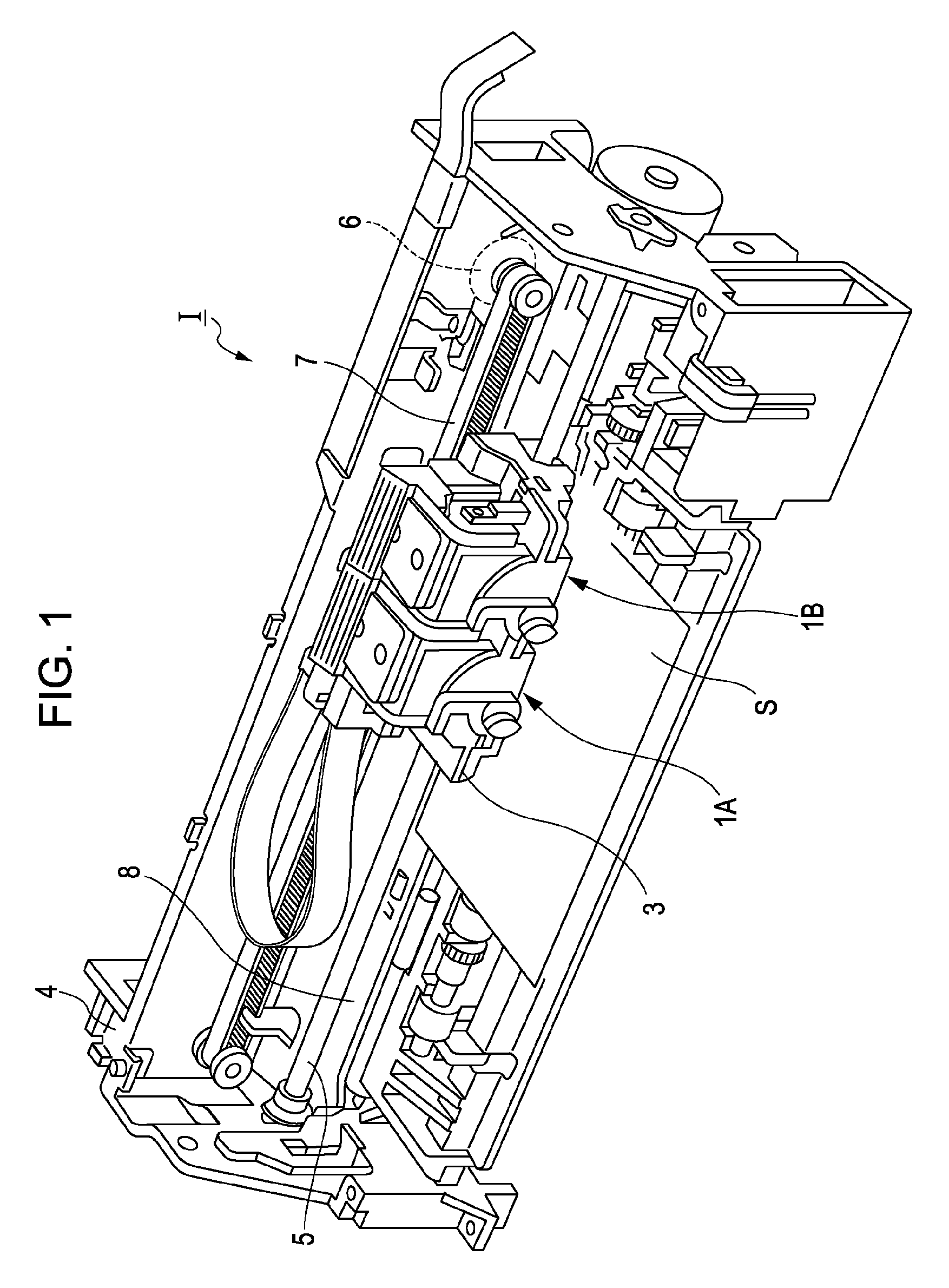
[0024]FIG. 1 is a schematic diagram showing an example of an ink jet recording apparatus. As shown in FIG. 1, record head units 1A and 1B are installed to the ink jet recording apparatus I as a liquid injecting apparatus. In other words, the record head units 1A and 1B are mounted to a carriage 3 of the ink jet recording apparatus I. In addition, the carriage 3 is installed to a carriage shaft 5, which is installed to a main body 4 of the ink jet recording apparatus I, to be movable in the direction of the shaft. These record head units 1A and 1B, for example, discharge a black ink composition and a color ink composition.

[0025]By transferring the driving force of a driving motor 6 to the carriage 3 through a plurality of gears not shown in the figure and a timing belt 7, the carriage 3 to which the record head units 1A and 1B are mounted is moved along the carriage shaft 5. In addition, a platen 8 is installed to the main body 4 along the carriage shaft 5, and a recording sheet S th...


PUM


Abstract

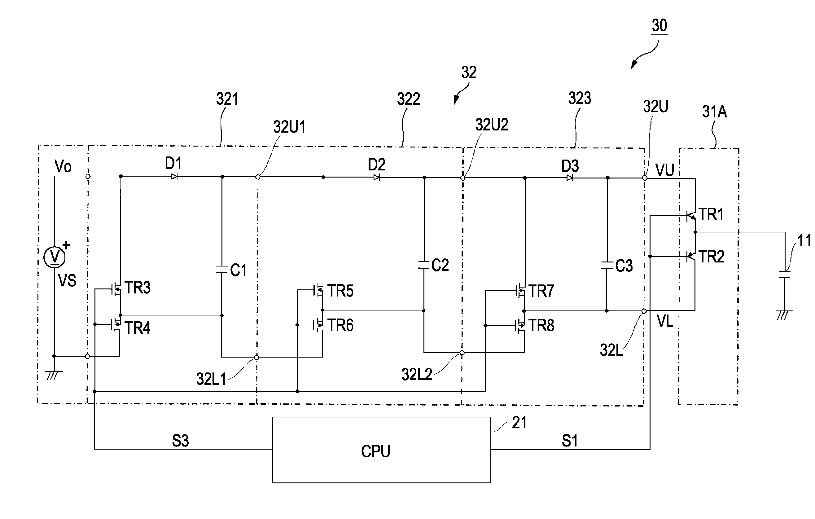
A driving circuit for a capacitive load includes a driving signal generating unit that generates a driving signal for driving the capacitive load by using a pair of driving transistors. A power source voltage generating unit generates high-voltage and low-voltage power source voltages that are higher and lower, respectively, than the voltage of the driving signal and applies the voltages to collectors of the driving transistors. The power source voltage generating unit includes a pair of power source transistors and a capacitor. The low-voltage power source voltage is generated in an output side of the power-source transistor pair as a voltage that is in a voltage region lower than that of the driving signal and follows the driving signal. The high-voltage power source voltage is output from a high-voltage terminal of the capacitor, is in a voltage region higher than that of the driving signal, and follows the driving signal.

Description

BACKGROUND[0001]1. Technical Field[0002]The present invention relates to a driving circuit for a capacitive load and a liquid injecting apparatus, and more particularly, to an ink jet record head that drives a piezoelectric element by using a driving signal having a trapezoidal shape and an ink jet recording apparatus having the ink jet record head.[0003]2. Related Art[0004]As liquid injecting apparatuses that perform a printing process or the like by injecting a liquid in accordance with supply of a driving signal and landing the liquid in a target, for example, ink jet recording apparatuses including an ink jet record head that injects ink droplets from a nozzle opening by using pressure that is generated by displacement of a piezoelectric element have been known. In the liquid injecting apparatus of this type, supply of a sufficient current is needed so as to operate a plurality of the piezoelectric elements without any problem. Accordingly, a driving signal of which current is a...

Claims


Application Information

Patent Timeline
IPC IPC(8): H03K3/00
CPCB41J2/04541B41J2/0457H03K4/94B41J2/0459B41J2/04581
Inventor KITAZAWA, KOJITAMURA, NOBORU
Owner SEIKO EPSON CORP
Learn More