
Projector

Active Publication Date: 2009-08-20
SEIKO EPSON CORP
View PDF3 Cites 0 Cited by
  • Summary
  • Abstract
  • Description
  • Claims
  • Application Information

AI Technical Summary

Benefits of technology

[0023]An advantage of some aspects of the invention is to provide a projector allowing downsizing of the combining optical system and the projection optical system even in the case of using a high resolution light modulation element.

Problems solved by technology

Therefore, in the projectors, growth of resolution of light modulation elements is in progress, and there is a tendency of ever-growing sizes of the light modulation elements.
The growth of the light modulation element sizes causes growth of sizes of overall optical systems, which incurs growth of the sizes of the projectors, and at the same time, increase in cost.
As described above, in the typical projector of the related art, the higher the resolution of the light modulation element is, the further the growth of the sizes of the cross dichroicprism 110 and the projection optical system 120 proceeds, which forms a factor causing decrease in the productivity of these optical elements and increase in the cost thereof.
It should be noted that although the FPC board can be curved or bent within an appropriate angle, if the FPC board is bent at an excessively acute angle or an excessive twist or the like is applied to the FPC board, a broken line or the like might be caused.
Therefore, the FPC board needs to be connected to other devices in a manner not providing the FPC board with folding with an excessively acute angle or an excessive twist.
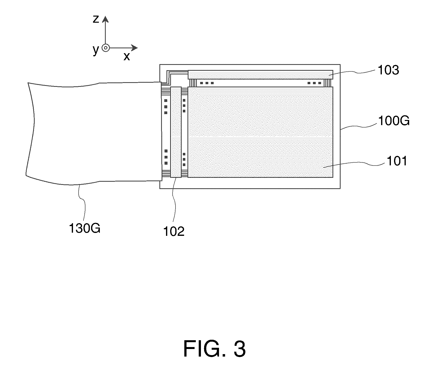
However, if it is arranged to connect the FPC boards simply to the short sides, there arises the following problem.
This causes growth in overall size of the light modulation element.
In other words, if it is attempted to execute the scanning direction conversion process with a single frame memory, when executing retrieving of the image data from the frame memory in order for setting the scanning direction for writing to be parallel to the short side direction, there might be caused a problem that, for example, the image data written as the image data for the subsequent frame exists in an area with the address for the data corresponding to a certain pixel on which the retrieving process is executed.

Method used


Image

  • Projector
  • Projector
  • Projector

Examples


first embodiment

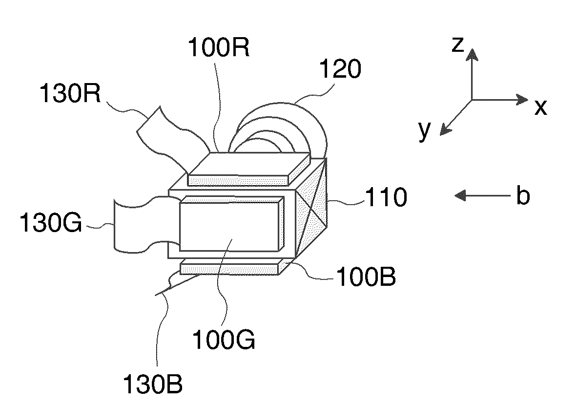
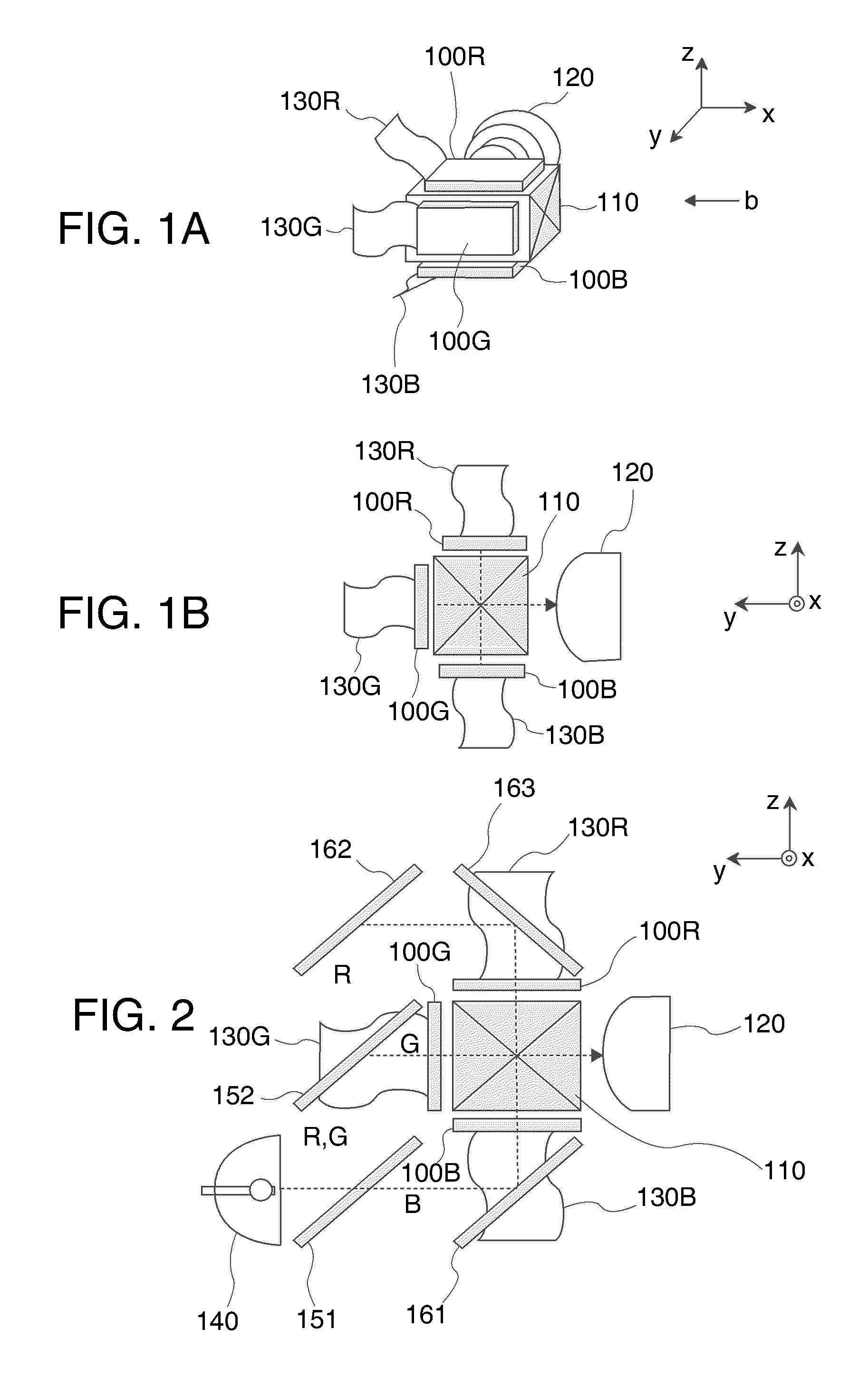
[0048]FIGS. 1A and 1B are diagrams showing a configuration of light modulation elements and an optical system in the periphery thereof in a projector according to a first embodiment, and in particular showing an image light forming optical system including a plurality of light modulation elements (assumed to be light modulation elements 100R, 100G, and 100B corresponding respectively to R, G, and B) and a cross dichroic prism 110 as a combining optical system, and a projection optical system 120. It should be noted that FIG. 1A is a perspective view, and FIG. 1B is a plan view corresponding to FIG. 1A, namely a diagram of the configuration shown in FIG. 1A viewed from a direction along the arrow b.

[0049]As shown in FIGS. 1A and 1B, in the projector according to the present embodiment of the invention, the light modulation elements 100R, 100G, and 100B corresponding respectively to the red light (R), the green light (G), and the blue light (B) are arranged so that the long sides ther...

second embodiment

[0071]FIG. 5 is a diagram showing a configuration of light modulation elements and an optical system and so on in the periphery thereof in the projector according to a second embodiment. The configuration of the light modulation elements and the optical system in the periphery thereof shown in FIG. 5 is substantially the same as that shown in FIGS. 1A and 1B, and what is different from that shown in FIGS. 1A and 1B is a cooling device 600 capable of cooling at least the light modulation elements 100R, 100G, and 100B provided thereto. It should be noted that the same constituents as those shown in FIGS. 1A and 1B are denoted with the same reference numerals.

[0072]As shown in FIG. 5, the projector according to the second embodiment has a structure in which the cooling air 610 from the cooling device 600 flows in a lateral direction, namely along the long side direction (the x-axis direction) of the light modulation elements 100R, 100G, and 100B. By thus flowing the cooling air in the ...


PUM


Abstract

A projector includes a plurality of light modulation elements adapted to modulate a plurality of colored light beams based on image data, a combining optical system adapted to combine the modulated colored light beams to emit image light, and a projection optical system adapted to project the image light emitted from the combining optical system on a projection screen. The light modulation elements are disposed with respect to the combining optical system so that long sides of the respective light modulation elements are adjacent to each other. Signal line cable boards adapted to provide the respective light modulation elements with signals, and coupled to short sides of the respective light modulation elements. A scanning direction of writing the image data to the light modulation elements is set to be parallel to a direction of the short side of an image display area in each of the light modulation elements.

Description

BACKGROUND[0001]1. Technical Field[0002]The present invention relates to a projector.[0003]2. Related Art[0004]Projectors are capable of displaying large screen images, and therefore, draw attention not only as display devices for presentation, but also as image display devices for displaying images required to have high quality, such as movies. Therefore, in the projectors, growth of resolution of light modulation elements is in progress, and there is a tendency of ever-growing sizes of the light modulation elements. The growth of the light modulation element sizes causes growth of sizes of overall optical systems, which incurs growth of the sizes of the projectors, and at the same time, increase in cost.[0005]The lower limit of the pitches of the pixels constituting the light modulation elements is generally believed to be in a range of 8 through 9 μm. Therefore, in order for obtaining the resolution of, for example, 4K2K (assumed to be 4096 pixels in the lateral direction×2160 pi...

Claims


Application Information

Patent Timeline
IPC IPC(8): H04N5/74
CPCH04N9/3105
Inventor ITO, TAKAFUMI
Owner SEIKO EPSON CORP
Learn More