Planar illumination device

a planar illumination and sidelight technology, applied in the direction of lighting and heating apparatus, printed element electric connection formation, instruments, etc., can solve the problems of increased radiation amount from led packages, insufficient direct radiation area, and insufficient radiation path for efficient radiation from the conductor of the fpc, so as to promote thinning of the apparatus, improve the effect of radiation efficiency and uniform brightness of the planar illumination devi

Inactive Publication Date: 2009-08-20
MINEBEA CO LTD
View PDF9 Cites 30 Cited by
  • Summary
  • Abstract
  • Description
  • Claims
  • Application Information

AI Technical Summary

Benefits of technology

[0016]According to the present invention, since the conductor pattern in the region where at least a through hole is formed is formed with a width larger than the width of the land portion, while a sectional area required for the conductor pattern is ensured, as many through holes provided for radiation as possible may be installed. It is only necessary that a width larger than the width of the land portion is ensured for the conductor pattern, and it may be a constant width substantially equal to the width of the land portion or it may be expanded to a...

Problems solved by technology

However, according to the conventional radiation structure, the heat of the point-like light source is mainly transmitted to a conductor of the FPC and radiated from the conductor further through a cover film of the FPC, and a radiation path for efficient radiation from the conductor of the FPC is not sufficient and a direct radiation area is not enough.
Particularly when a large-current type LED is used as the point-like light source, a radiation amount from the LED package is also increased, and the problem becomes more remarkable.
On the other hand, it is possible to improve the radiation characteristic by using a circuit board constructed by a material with high heat conductance such as aluminum, co...

Method used


Image

  • Planar illumination device
  • Planar illumination device
  • Planar illumination device

Examples


Embodiment Construction

[0037]Embodiments of the present invention will be described below based on the attached drawings. Here, the same portions or portions corresponding to the prior art are indicated by the same reference numerals and detailed description will be omitted.

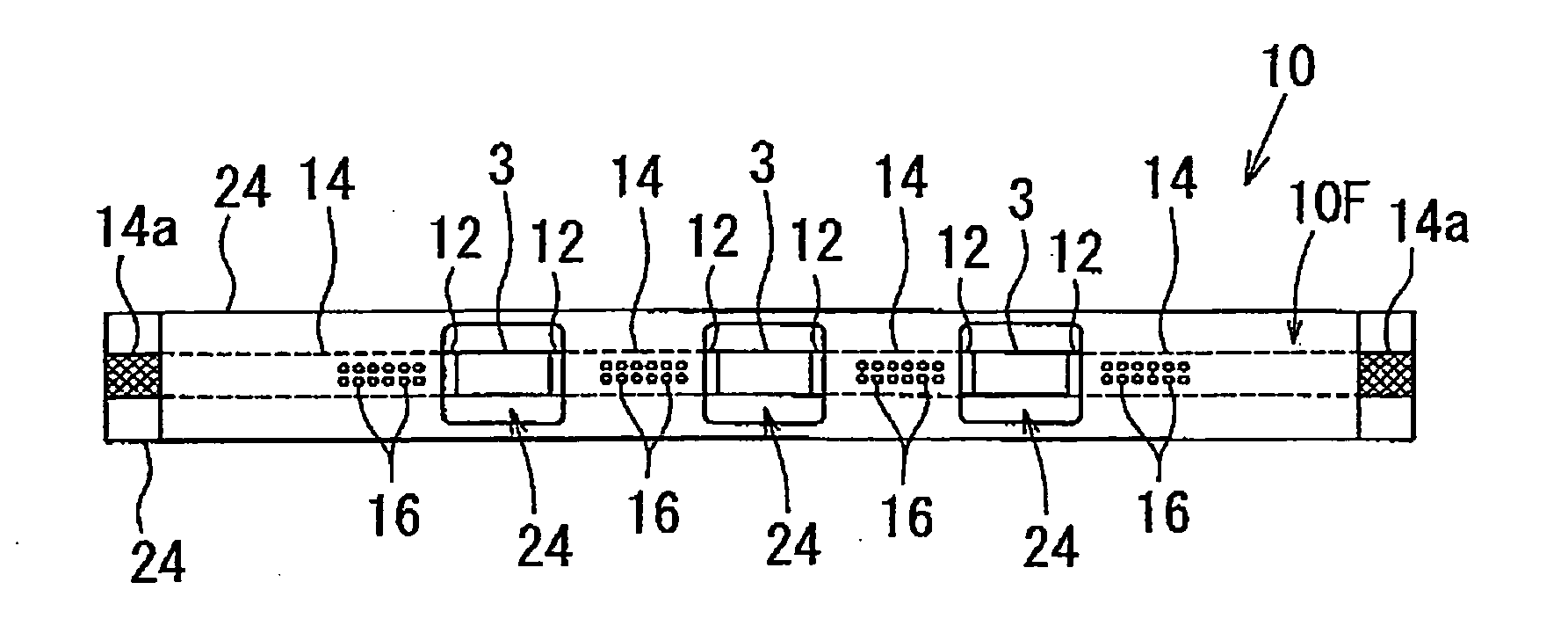
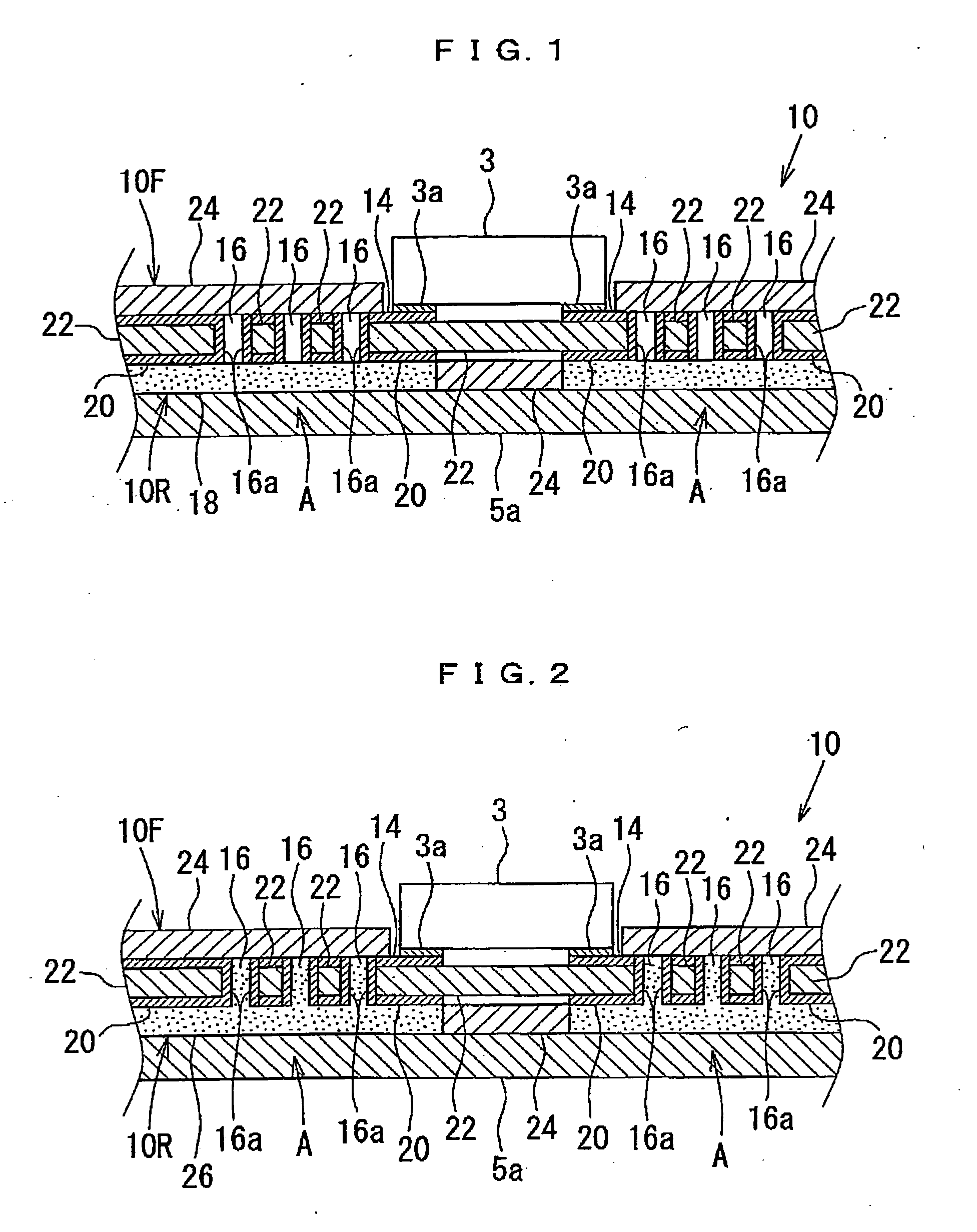
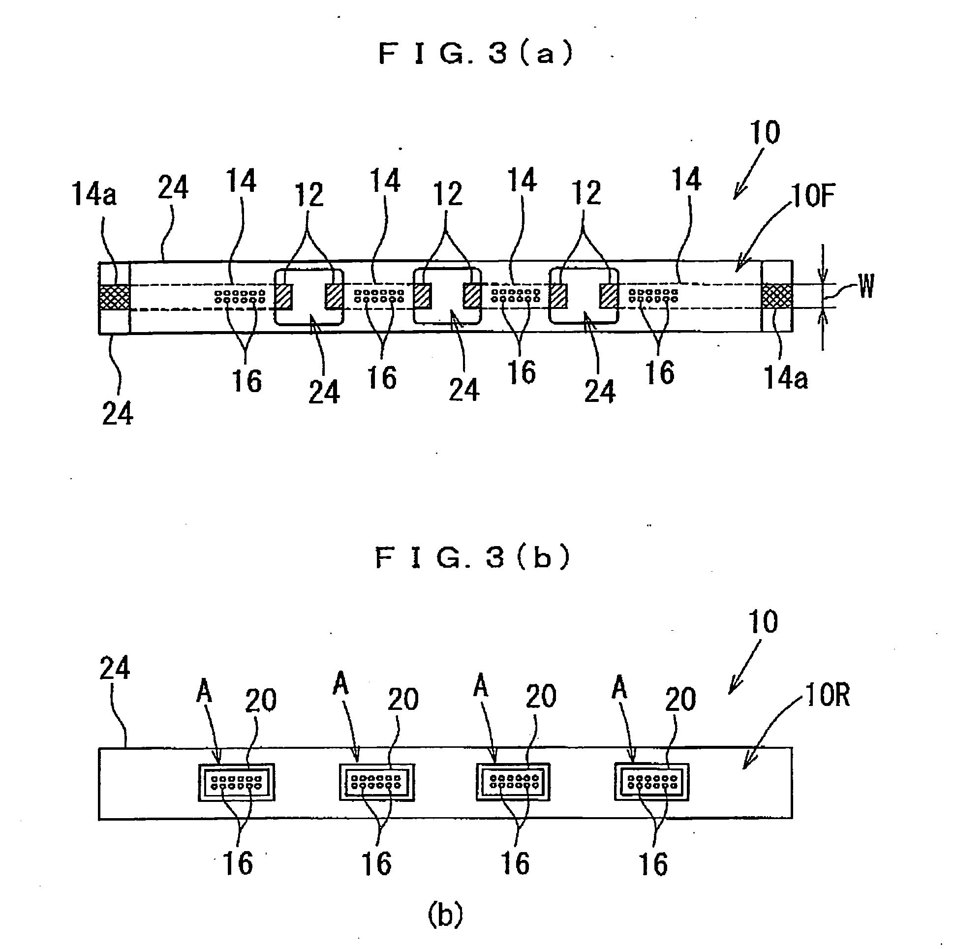
[0038]FIG. 1 shows a flexible print circuit board (FPC) 10 on which a large-current type LED is surface-mounted as the point-like light source 3 in a section of a planar illumination device according to the embodiment of the present invention. The FPC 10 has the same basic configuration such as outline and thickness as the FPC 4 shown in FIG. 5. Specifically, as shown in FIGS. 3A and 3B, a conductor pattern 14 continuing to a land portion 12 where an electrode terminal 3a of the point-like light source 3 is mounted on a front side face 10F is formed. This conductor pattern 14 is formed with the same constant width as a width W of the land portion 12. In order to effectively achieve self-alignment in the biaxial direction in a plane of ...


PUM


Abstract

More efficient radiation of heat from a point-like light source is enabled, and thinning is promoted, while higher and more uniform brightness of a planar illumination device is accommodated. A radiation path is formed through which the heat generated from the point-like light source is transmitted to a radiator plate made of metal through an electrode terminal of the point-like light source, a land portion of a front side face of an FPC, a through hole of a conductor pattern, and a high heat-conductive resin. The radiation path for efficient radiation from a conductor pattern of the FPC to the radiator plate made of metal is extended, and direct radiation area is sufficiently ensured. Particularly even if a large-current type LED is used for the point-like light source, sufficient radiation effect can be obtained. Also, since freedom in wiring pattern on the FPC and freedom of outline are not different from a conventional FPC at all, a demand for thinning of the planar illumination device can be sufficiently satisfied.

Description

TECHNICAL FIELD[0001]The present invention relates to a side-light-type planar illumination device and particularly to a planar illumination device used as illuminating means of a liquid crystal display device.BACKGROUND ART[0002]As an auxiliary light source for a liquid crystal display device used for a cellular phone or the like, a side-light type planar illumination device in which a primary light source is arranged on a side end face of a light guide plate is mainly used (hereinafter the side end face on which the primary light source is arranged is also called as an incoming-light face). As the primary light source of a side-light-type planar illumination device, a cold-cathode tube lamp has been used, but currently, a point-like light source such as a white LED which is more excellent in handling, easier in size reduction and better in impact resistance than the cold-cathode tube lamp is used in many cases. Application fields of the planar illumination device using such a poin...

Claims


Application Information

Patent Timeline
IPC IPC(8): F21V7/22F21V29/00
CPCG02B6/0085H05K1/0206H05K3/0061H05K3/281H05K2201/10106H05K3/42H05K2201/0209H05K2201/09481H05K2201/0959H05K3/386
Inventor SATOH, MAKOTOOHNO, YASUO
Owner MINEBEA CO LTD
Why Eureka
Try Eureka