Sigmoidoscope with optical coupling element

a technology of coupling element and sigmoidoscope, which is applied in the field of medical instruments, can solve the problems of reusable components of sigmoidoscope, potential cross-contamination and infection, and relatively expensive components of the fibre-optic head and hinged window and light source, and achieve the effect of reducing the risk of contamination of the optical head

Inactive Publication Date: 2009-08-20
DALTRAY
View PDF11 Cites 17 Cited by
  • Summary
  • Abstract
  • Description
  • Claims
  • Application Information

AI Technical Summary

Benefits of technology

[0017]a coupling element having a proximal end for releasable connection to the observation end of the speculum, a distal end adapted for releasable connection to an optical head, and an optically transparent observation window effectively isolating the distal end from the proximal end;
[0018]the coupling element being adapted upon connection to substantially seal the observation end of the speculum and to preventing direct contact between the optical head and the speculum, without visually

Problems solved by technology

The fibre-optic head together with the hinged window and the light source are relatively expensive components and are therefore not disposed of.
This practice gives rise to the potential for cross-contamination and infection from the reusable components of the sigmoidoscope, most notably the insufflation bulb and the fibre-optic head.
However, a problem remained in relation to the obturator, which has not hitherto been addressed by the applicant's earlier invention, or the prior art.
However, a fundamental problem with known sigmoidoscope designs is that as the obturator is withdrawn, it can and in practice almost inevitably does inadvertently come into contact with non-disposable parts of the sigmoidoscope, or with disposable parts that subsequently contact non-disposable parts.
T

Method used


Image

  • Sigmoidoscope with optical coupling element
  • Sigmoidoscope with optical coupling element
  • Sigmoidoscope with optical coupling element

Examples


Embodiment Construction

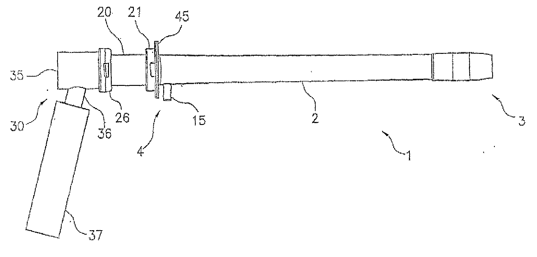
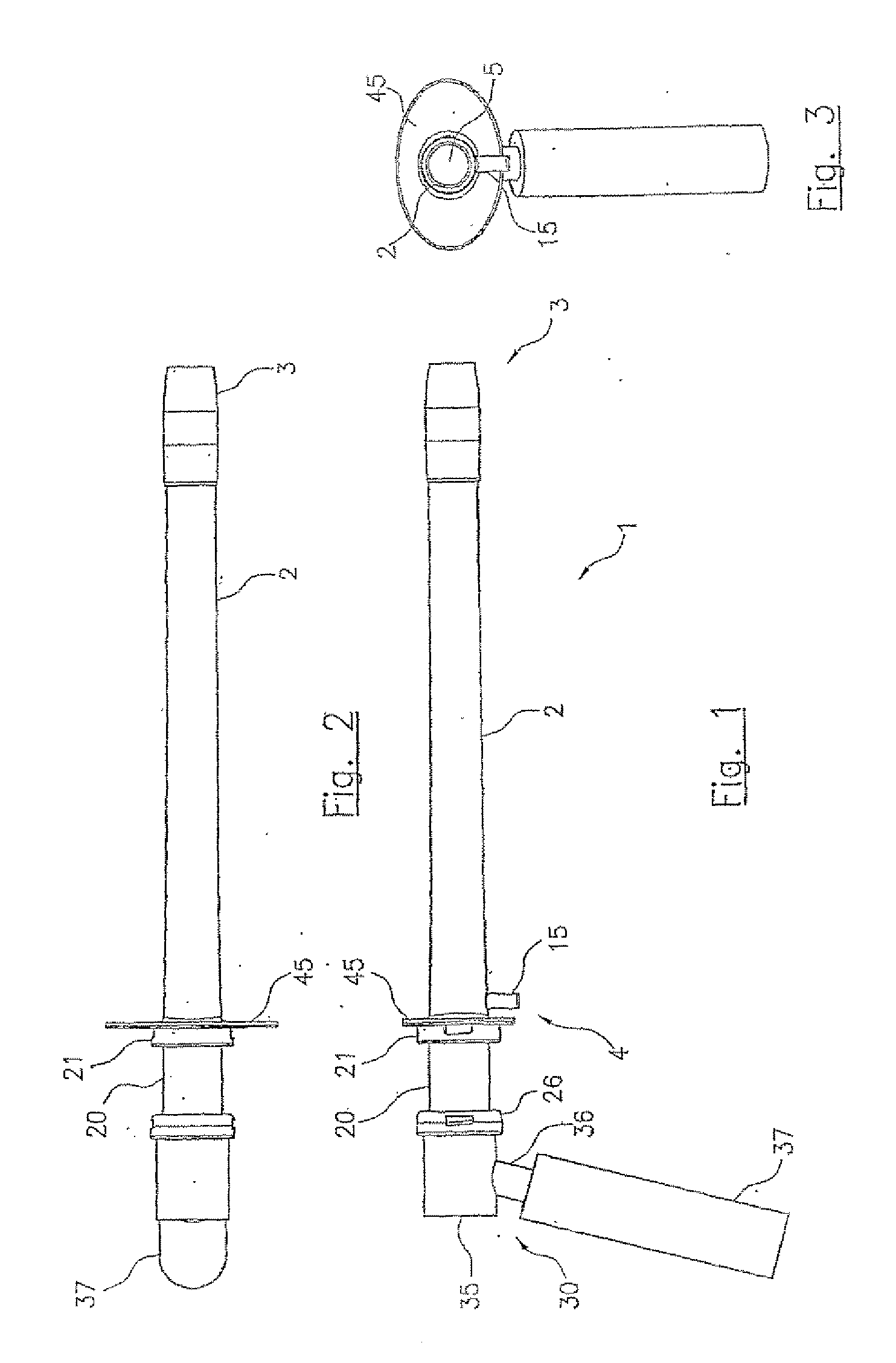
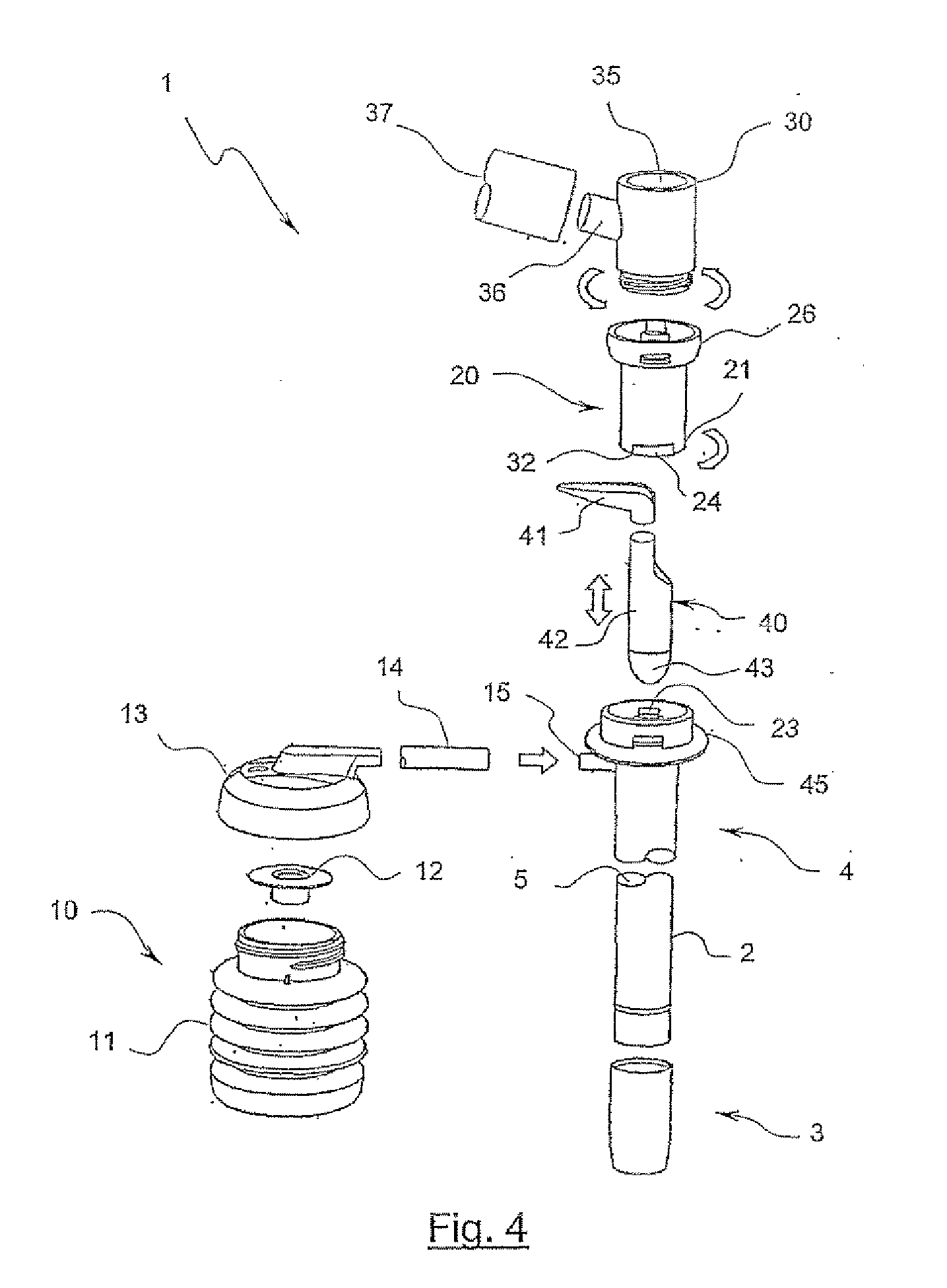
[0046]Referring initially to FIGS. 1 to 9 of the drawings, the invention provides a medical instrument adapted for use as a sigmoidoscope 1. The sigmoidoscope includes a generally tubular body in the form of a speculum 2, having a forward insertion end 3, a rearward observation end 4 and a lumen 5 defining a substantially unobstructed viewing path between the observation and insertion ends.

[0047]The sigmoidoscope further includes manually operable insufflation means 10 (see FIG. 4), including resiliently deformable bellows 11, valve mechanism 12, bellows cap 13 and a flexible connection tube 14. The connection tube extends from the bellows cap to a tubular spigot 15 extending radially outwardly from the speculum, to convey the insufflation medium, in this case air, from the bellows directly to the interior region or lumen 5 of the speculum. It will be appreciated, however, that the insufflation tube may be releasably connected to the speculum by any suitable means other than a spigo...


PUM


Abstract

A sigmoidoscope (1) adapted for use in conjunction with a removable obturator to facilitate internal examination of the sigmoid colon of a patient. The sigmoidoscope includes a generally tubular speculum (2) having a sidewall defining a forward insertion end (3), a rearward observation end (4) and an internal lumen (5). The lumen (5) defines a substantially unobstructed viewing path between the observation end and the insertion end. Manually operable insufflation means (10) in fluid communication with the lumen of the speculum are provided for insufflation of the sigmoid colon with an insufflation medium. A coupling element (20) has a proximal end (21) for releasable connection to the observation end (4) of the speculum, a distal end (26) adapted for releasable connection to an optical head (30), and an optically transparent observation window (32) effectively isolating the distal end from the proximal end. The coupling element (20) is adapted upon connection to substantially seal the observation end of the speculum and to prevent direct contact between the optical head (30) and the speculum, without visually obstructing the viewing path.

Description

FIELD OF THE INVENTION[0001]This invention relates to medical instruments, and in particular to an instrument adapted for insertion into bodily cavities. The invention has been developed primarily as a sigmoidoscope for use in examination of the bowel cavity of a patient and for sigmoidoscopy generally.BACKGROUND OF THE INVENTION[0002]The following description of the prior art is provided to place the invention in an appropriate technical context, and to enable the advantages flowing from it to be fully appreciated. References to the prior art should not, however, be interpreted as indicating that such art is well known, or forms part of common general knowledge, in the field.[0003]It is frequently necessary for specialised medical practitioners to inspect the sigmoid colon or rectum of a patient. This procedure is commonly conducted with a rigid sigmoidoscope, which in the past typically consisted of a metal tube or speculum adapted at one end for insertion into the rectum of a pat...

Claims


Application Information

Patent Timeline
IPC IPC(8): A61B1/31A61B1/06
CPCA61B1/31A61B1/0669A61B1/00128A61B1/00126
Inventor LUBOWSKI, DAVIDMARSH, PETER CRISPIN
Owner DALTRAY
Why Eureka
Try Eureka