
Hand-held system and method for detecting impaired electric power equipment

a technology of impaired electrical equipment and hand-held devices, which is applied in the direction of electric devices, instruments, transportation and packaging, etc., can solve the problems of limiting or disrupting the operation of the electrical system, electromagnetic radiation may interfere with the operation of other electrical systems, and many sophisticated electrical systems are becoming increasingly sensitive to the effects of electromagnetic radiation

Active Publication Date: 2009-08-20
EXACTOR INC
View PDF18 Cites 24 Cited by
  • Summary
  • Abstract
  • Description
  • Claims
  • Application Information

AI Technical Summary

Benefits of technology

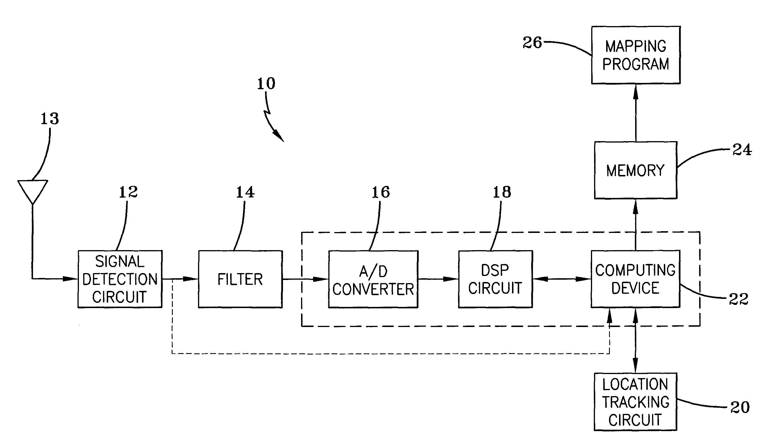
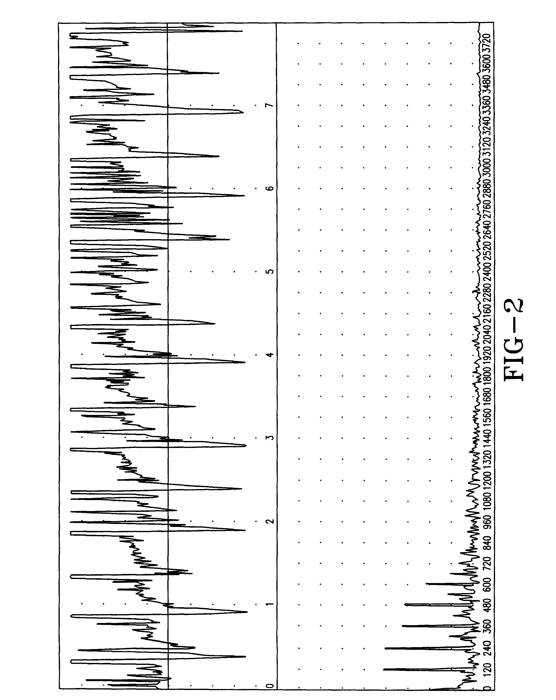
[0012]Exemplary embodiments of the present invention are directed to a system and method for detecting impaired electrical equipment. An exemplary embodiment of the present invention may receive electromagnetic radiation and process the resulting signal. For example, signal processing in some embodiments of the present invention may be used to identify electromagnetic radiation having a particular characteristic. Exemplary embodiments may utilize a wide and flat passband filter to combat and eliminate the problem of standing waves. The use of a wide filter with a flat passband causes a cancellation effect among various frequencies within the passband when the EMI detector is not at the exact source. This results in a EMI detector that may be immune to the false source phenomenon that other EMI detectors experience. This allows exemplary embodiments to locate the disruption more efficiently. To aid with location of disruption, exemplary embodiments take readings at multiple frequencies and use an averaging technique to guide a user to the location. This averaging function may occur inherently as a function of the wide filter employed. Furthermore, an exemplary embodiment of the present invention may also include the determination of the time and / or location during testing. As a result, an exemplary embodiment of the present invention may be useful for stationary and / or mobile testing of an electrical system.

Problems solved by technology

The underlying cause of the electromagnetic radiation may limit or disrupt the operation of the electrical system that is emitting the electromagnetic radiation.
Moreover, electromagnetic radiation may also interfere with the operation of other electrical systems.
In fact, many sophisticated electrical systems are becoming increasingly sensitive to the effects of electromagnetic radiation.
In addition, impaired electrical equipment may be the cause of an increased level of electromagnetic radiation.
Regardless of whether the cause of electromagnetic radiation is intentional or inadvertent, hostile or friendly, or caused by jamming devices, malfunctioning equipment, or improper system operation, the resulting electromagnetic radiation can have detrimental impact on the operation of electronics and other electrical systems.
However, the development of new shielding technologies has not kept pace with the development of new electrical systems.
Thus, the development of shielding has been relatively stagnant in recent history.
Compounding this problem is the fact that EMI detection techniques have not advanced rapidly enough in light of the development of new types of electrical systems.
There are currently few research and development activities to develop new devices to identify the causes of EMI.
As a result there are little to no quality commercial EMI diction devices available.
Currently commercial EMI detectors suffer from poor construction and lack the tolerances necessary to reliably detect and locate EMI.
Commercial EMI detectors only work with a particular frequency and lack the variety necessary to be effective.
Another problem with most commercial EMI detectors is that they are susceptible to standing waves.
This susceptibility to standing waves interferes with the EMI detectors ability to locate the disturbance.
As a result, EMI is an increasing problem.
Power line arcing is one example of a cause of EMI.
As a result of the high voltage, power line arcing may be destructive, and it may indicate that certain electrical equipment is in an impaired condition.
In fact, any type of arcing may indicate that electrical equipment is in an impaired condition.
For example, a small gap between components of energized electrical equipment may lead to arcing, wherein an electrical charge builds up and discharges across the gap.
The cause of a gap may simply be due to expansion and contraction or corrosion of the equipment.
As a result, small gaps in the electrical equipment can be very difficult to identify.
Compounding the difficulty is the fact that some electrical equipment such as power lines may be located well above ground level and energized with high voltage, making it impractical or inefficient for electrical utility personnel to visually inspect each structure or other elevated equipment in an attempt to locate an impaired piece of electrical equipment.
Impaired equipment can still be difficult to locate even if the equipment is located near ground level.
For instance, multiple pieces of electrical equipment in a general area such as a room, a factory building, or even a general outside area can hinder the detection of an impaired piece of equipment.
As a result, the location of impaired electrical equipment may be difficult to identify.

Method used


Image

  • Hand-held system and method for detecting impaired electric power equipment
  • Hand-held system and method for detecting impaired electric power equipment
  • Hand-held system and method for detecting impaired electric power equipment

Examples


examples

[0044]One exemplary embodiment of a system of the present invention is a versatile tool for identifying the source of electromagnetic interference that may be used in different ways such as described below:[0045]1. In one example, a system may be used to evaluate a utility pole from the ground. For instance, when patrolling for EMI, the results may not clearly point to a single pole. In this case, an exemplary embodiment of a system may help to determine which pole(s) actually contain EMI sources.[0046]2. Use an EMI patrolling method (such as an exemplary system of the present invention that is transported by a vehicle) to find the general location of the strongest EMI level for a given area.[0047]3. Begin by setting the exemplary system's attenuation switch to 0 db and gain control to 10. Approach the pole nearest to the maximum signal location identified in step 1.[0048]4. Position the antenna of the exemplary system against the wood of the pole or against the pole ground. If a st...


PUM


Abstract

A hand-held system and method for detecting impaired electric power equipment. An exemplary embodiment may receive electromagnetic radiation and process the resulting signal. For example, signal processing may be used to identify electromagnetic radiation having a particular pattern that is characteristic of electric power equipment. Furthermore, an embodiment may determine the time and / or location during testing. As a result, an exemplary embodiment may be useful for stationary and / or mobile testing of an electrical system.

Description

[0001]This is a continuation-in-part of U.S. application Ser. No. 11 / 139,192, filed May 27, 2005, which is hereby incorporated by reference in its entirety.BACKGROUND AND SUMMARY OF THE INVENTION[0002]Exemplary embodiments of the present invention relate generally to a system and method for identifying impaired electrical equipment. More particularly, some exemplary embodiments of the present invention relate to a system and method for detecting impaired electric power equipment. Exemplary embodiments of the present invention may also be useful for testing various other types of electrical systems. Furthermore, exemplary embodiments of the present invention may be useful for stationary and / or mobile testing of various types of electrical systems.[0003]Power generation, distribution, transmission, and substation systems are just some examples of electrical systems. Some other examples of electrical systems include radio systems, communication systems, control systems, industrial elec...

Claims


Application Information

Patent Timeline
Patent Type & Authority Applications(United States)
IPC IPC(8): G01R21/00
CPCG01R29/0871G01R31/088G01R31/001
Inventor MCCULLOUGH, JASONHAYES, RAYMOND M.KLINECT, DAVID A.KILLINGSWORTH, DON K.
Owner EXACTOR INC
Learn More