Superconducting magnet, magnetic resonance imaging apparatus, and method of calculating coolability of cryo-cooler

a magnetic resonance imaging and superconducting magnet technology, applied in the field of magnetic resonance imaging apparatus, can solve the problems of deteriorating vaporization and consumption, and heat penetration into the cryostat, and achieve the effect of accurate heat penetration amount and coolability of the cryosta

Inactive Publication Date: 2009-08-20
HITACHI LTD
View PDF4 Cites 11 Cited by
  • Summary
  • Abstract
  • Description
  • Claims
  • Application Information

AI Technical Summary

Benefits of technology

[0025]According to the present invention, it is possible to immediately grasp an accurate heat penetration amount into the cryostat. Therefore, without depending on the state and environment of the system, the heat penetration amount into the cryostat and the coolability of the cryo-cooler are balanced properly, and the consumption of the refrigerant is rendered to be zero substantially.
[0026]A basic effect of the present invention includes specific effects as the following in the specific situations as describe below:
[0027]In addition, according to the present invention, the heat penetration amount into the cryostat and the coolability of the overall system including the cryostat are immediately grasped, and the result can be presented to an operator or a maintenance manager.

Problems solved by technology

In any type of the superconducting magnet, there is a problem that heat penetration into the cryostat due to conduction and radiation, vaporizes and consumes a liquid helium refrigerant used for cooling the superconducting coil.
This is because, the coolability of the cryo-cooler is deteriorated over time, and it is necessary to suppress the helium consumption, in association with the heat penetration amount into the cryostat and the deterioration of the coolability of the cryo-cooler.

Method used


Image

  • Superconducting magnet, magnetic resonance imaging apparatus, and method of calculating coolability of cryo-cooler
  • Superconducting magnet, magnetic resonance imaging apparatus, and method of calculating coolability of cryo-cooler
  • Superconducting magnet, magnetic resonance imaging apparatus, and method of calculating coolability of cryo-cooler

Examples


first embodiment

[0029]A first embodiment of the present invention will be explained. The present embodiment is to control a pressure within a helium container to be at a constant level, and a helium gas outflow from the helium container is measured so as to accurately obtain a heat penetration amount into the helium container. Then, an optimum cryo-cooler is selected, which has coolability exceeding the heat penetration amount being obtained and incorporated into a superconducting magnet, thereby configuring a cryo system with an optimum coolability, being appropriate for each individual difference of the superconducting magnet. With reference to FIG. 1 to FIG. 5, the present embodiment will be explained in detail.

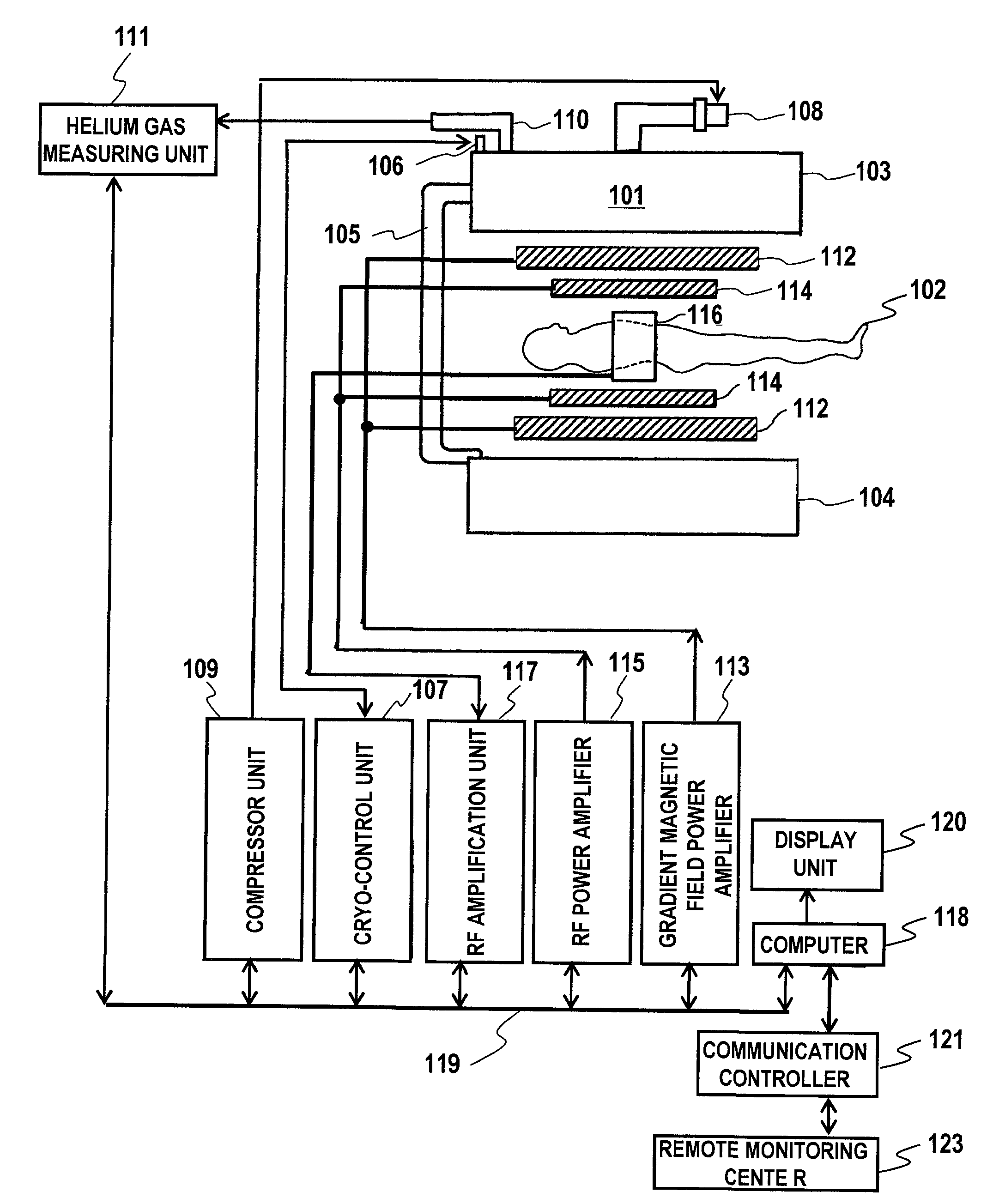
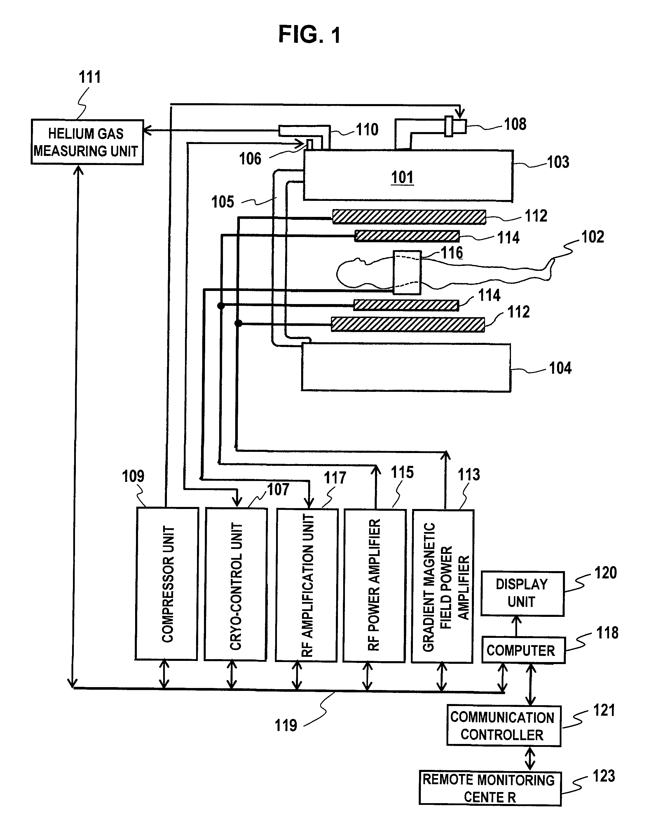
[0030]Firstly, an overview of the overall configuration of the present embodiment will be explained with reference to FIG. 1. FIG. 1 is a diagram showing the overall configuration of a superconducting MRI apparatus employing a superconducting magnet to which the present invention is appli...

second embodiment

[0083]Next, a second embodiment of the present invention will be explained. In the present embodiment, the measurement of the helium gas flow rate and the control of the heating value of the heater are performed at a constant frequency, and the maintenance or replacement of the cryo-cooler is notified as well. The MRI apparatus, the measurement of the helium gas flow rate, and the control of the heating value in the present embodiment are the same as those in the first embodiment. Therefore, detailed explanations thereof will not be tediously made, and only different points will be explained in detail in the following. Hereinafter, the present embodiment will be explained in detail with reference to FIG. 1 and FIG. 3.

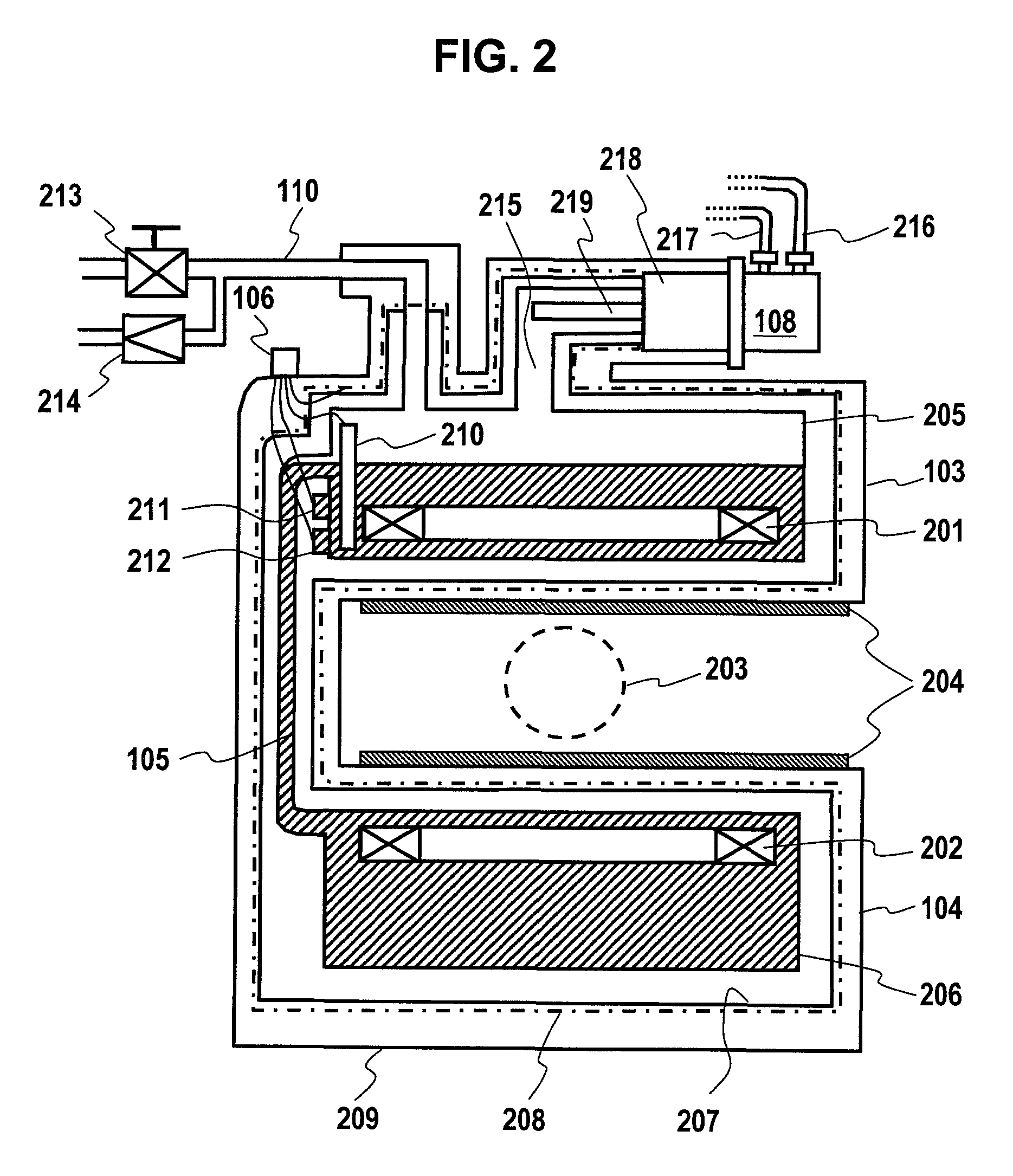
[0084]In the present embodiment, as shown in FIG. 1 and FIG. 3, the helium gas measuring unit 111 is connected to the service port 110 of the superconducting magnet 101 on a steady basis. The valve 213 and the unidirectional valve 214 are respectively provided with driv...

third embodiment

[0088]Next, a third embodiment of the present invention will be explained. The present embodiment is to perform the measurement of the helium gas flow rate and the control of the heating value of the heater at regular intervals, according to a remote monitoring, and grasp whether or not it is necessary to perform maintenance or replacement of the cryo-cooler. Since the MRI apparatus, the measurement of the helium gas flow rate, and the control of the heating value are the same as those in the first embodiment, detailed explanations thereof will not be tediously made, and only different points will be explained in detail in the following. Hereinafter, the present embodiment will be explained with reference to FIG. 1.

[0089]As shown in FIG. 1, the computer 118 of the present embodiment is connected to the remote monitoring center 123 via the communication controller 121, such as a modem or LAN. The computer 118 notifies the remote monitoring center 123 of operation management informati...


PUM


Abstract

An MRI apparatus is provided in which a heat quantity penetrating into the helium tank of a superconducting magnet can be grasped to select a cryo-cooler to be incorporated, whereby consumption of liquid helium is suppressed and a static magnetic field is generated stably. The superconducting magnet includes a superconducting coil, containers 209 and 203 for accommodating the superconducting coil and a refrigerant, a cooler 208 for liquefy gas once again, the gas having been obtained by vaporizing the refrigerant in the containers, and a means for measuring the amount of vaporized refrigerant, while keeping the pressure in the containers at a constant level. The heat quantity penetrating into the containers and the coolability of the cooler are measured accurately, thereby enabling a combination in which the coolability of the cooler to be combined has capacity more than the heat penetration amount.

Description

TECHNICAL FIELD[0001]The present invention relates to a magnetic resonance imaging apparatus (referred to as “MRI apparatus”) employing a superconducting magnet, and in particular, it relates to a selection of a cryo-cooler having necessary coolability.BACKGROUND ART[0002]An MRI apparatus that places a test subject in a homogenous magnetic field space for conducting a medical diagnosis according to a nuclear magnetic resonance (referred to as “NMR”) signal is utilized in a medical institution, just like using a CT apparatus and an RI apparatus to conduct a conventional examination. In particular, an examination using the MRI apparatus shows a superior capability for detecting a lesion. This enhanced lesion detection capability is achieved because an MRI image enables various examination methods to produce not only a diagnostic image being simply morphologic, but also an image representing functional diagnostic information such as metabolism.[0003]In order to acquire an MRI image tha...

Claims


Application Information

Patent Timeline
Patent Type & Authority Applications(United States)
IPC IPC(8): G01R33/3815F17C3/00G06F15/00
CPCG01R33/3804H01F6/04G01R33/3815G01R33/3806
Inventor TSUDA, MUNETAKA
Owner HITACHI LTD
Why Eureka
Try Eureka