
Rotor shaft for an electric machine and electric machine

A technology for rotor shafts and steering parts, applied in the manufacture of stator/rotor bodies, electromechanical devices, electrical components, etc., can solve problems such as cooling fluid friction loss, achieve high design freedom, reduce inertia, and provide design freedom Effect

Active Publication Date: 2019-08-09
BAYERISCHE MOTOREN WERKE AG
View PDF17 Cites 0 Cited by
  • Summary
  • Abstract
  • Description
  • Claims
  • Application Information

AI Technical Summary

Problems solved by technology

[0004] Furthermore, it is known from the prior art that the cooling fluid present in the axial bore produces frictional losses when the rotor shaft rotates

Method used


Image

  • Rotor shaft for an electric machine and electric machine
  • Rotor shaft for an electric machine and electric machine
  • Rotor shaft for an electric machine and electric machine

Examples


Embodiment Construction

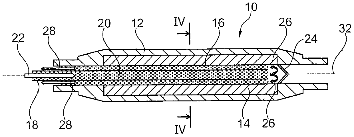
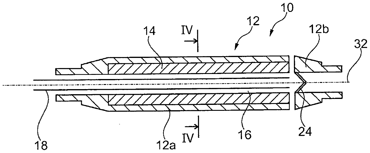
[0033] figure 1 A rotor shaft 10 for an electric machine (not shown in detail) is shown, comprising a rotor shaft base body 12 and a rotor shaft core 14 arranged in the rotor shaft base body 12 and connected to the rotor shaft base body 12 .

[0034] Furthermore, a cooling chamber 16 is provided in the rotor shaft 10 , which in the embodiment shown is an approximately axial central bore.

[0035] A cooling fluid nozzle 18 is inserted into the cooling chamber 16 , through which cooling fluid 20 is introduced into the cooling chamber 16 . The insertion direction is indicated by arrow 22 .

[0036] The cooling chamber 16 extends essentially continuously in the rotor shaft 10 , but is delimited at the end facing away from the cooling fluid nozzle 18 by a cooling fluid deflector 24 . This cooling fluid deflector deflects the cooling fluid 20, as indicated by the arrow 26, so that the cooling fluid exits the cooling fluid again on the same side of the rotor shaft 10 on which the c...


PUM


Abstract

A rotor shaft (10) for an electric machine is described, which comprises a rotor shaft main part (12) and a rotor shaft core (14) arranged therein and connected to the rotor shaft main part (12). Therotor shaft (10) also comprises a cooling cavity (16) running substantially axially for conducting a cooling fluid (20). The rotor shaft core (14) is made of a different material from the rotor shaftmain part (12). An electric machine having a rotor shaft (10) of this type is also presented.

Description

technical field [0001] The invention relates to a rotor shaft for an electric machine and to an electric machine. Background technique [0002] In the prior art, rotor shafts for electric machines are usually equipped with so-called hollow shaft cooling. Here, the shaft is provided with an axial bore, into which a cooling fluid, such as water, is introduced. [0003] The cooling fluid can be introduced into the axial bores by means of so-called cooling fluid nozzles. In this case, the axial bore can be a blind bore. The cooling fluid then exits on the same side of the shaft where it was introduced into the shaft through the cooling fluid nozzles. [0004] Furthermore, it is known from the prior art that the cooling fluid present in the axial bore produces frictional losses when the rotor shaft rotates. Accordingly, the axial bore for the cooling fluid is provided with a relatively small diameter in the rotor shaft rotating at high speed. Frictional losses through the co...

Claims


Application Information

Patent Timeline
Patent Type & Authority Applications(China)
IPC IPC(8): H02K1/32H02K9/19H02K15/02
CPCH02K1/32H02K15/02H02K2209/00H02K5/207H02K9/197H02K7/003H02K9/19
Inventor E·巴蒂J·布卢姆M·朗D·罗斯H·乌尔布里希
Owner BAYERISCHE MOTOREN WERKE AG
Learn More