Modular Element With Photovoltaic Module

a technology of photovoltaic modules and modules, applied in photovoltaics, solar heat collectors for particular environments, heat collector mounting/support, etc., can solve the problems of difficult sealing and thermal protection of the roof in its entirety, complex construction of such a structure, and complex integration of solar panels on such a structure. achieve the effect of easy production

Inactive Publication Date: 2009-08-27
PHOTOWATT INT
View PDF25 Cites 21 Cited by
  • Summary
  • Abstract
  • Description
  • Claims
  • Application Information

AI Technical Summary

Benefits of technology

[0005]The present invention aims to solve completely or partly these drawbacks by providing a modular construction element that makes it easier to produce such a type of roof and to integrate solar panels. For this purpose, the subject of the invention is a modular construction element used to close a building roof, in particular a flat roof, comprising a wall having a first face inclined with respect to a horizontal plane, having at least one transparent or translucent portion suitable for allowing natural light to illuminate the inside of the building; a second face inclined with respect to a horizontal plane, of opposite orientation to the first face, having at least one solar panel comprising at least one photovoltaic module; and at least part of the faces of the modular element comprising at least one thermal and / or acoustic insulation layer.

Problems solved by technology

However, the construction of such a roof having several separate construction components is complicated and its design by architects depends on the dimensions of the building.
This is because the integration of solar panels on such a structure is complicated if it is desired to ensure cooling, insulation and positioning conditions that allow the panel to operate satisfactorily.
In addition, once the components have been positioned, the sealing and the thermal protection of the roof in its entirety are tricky to achieve given the heterogeneous assembly formed by this roof.

Method used


Image

  • Modular Element With Photovoltaic Module
  • Modular Element With Photovoltaic Module
  • Modular Element With Photovoltaic Module

Examples


Embodiment Construction

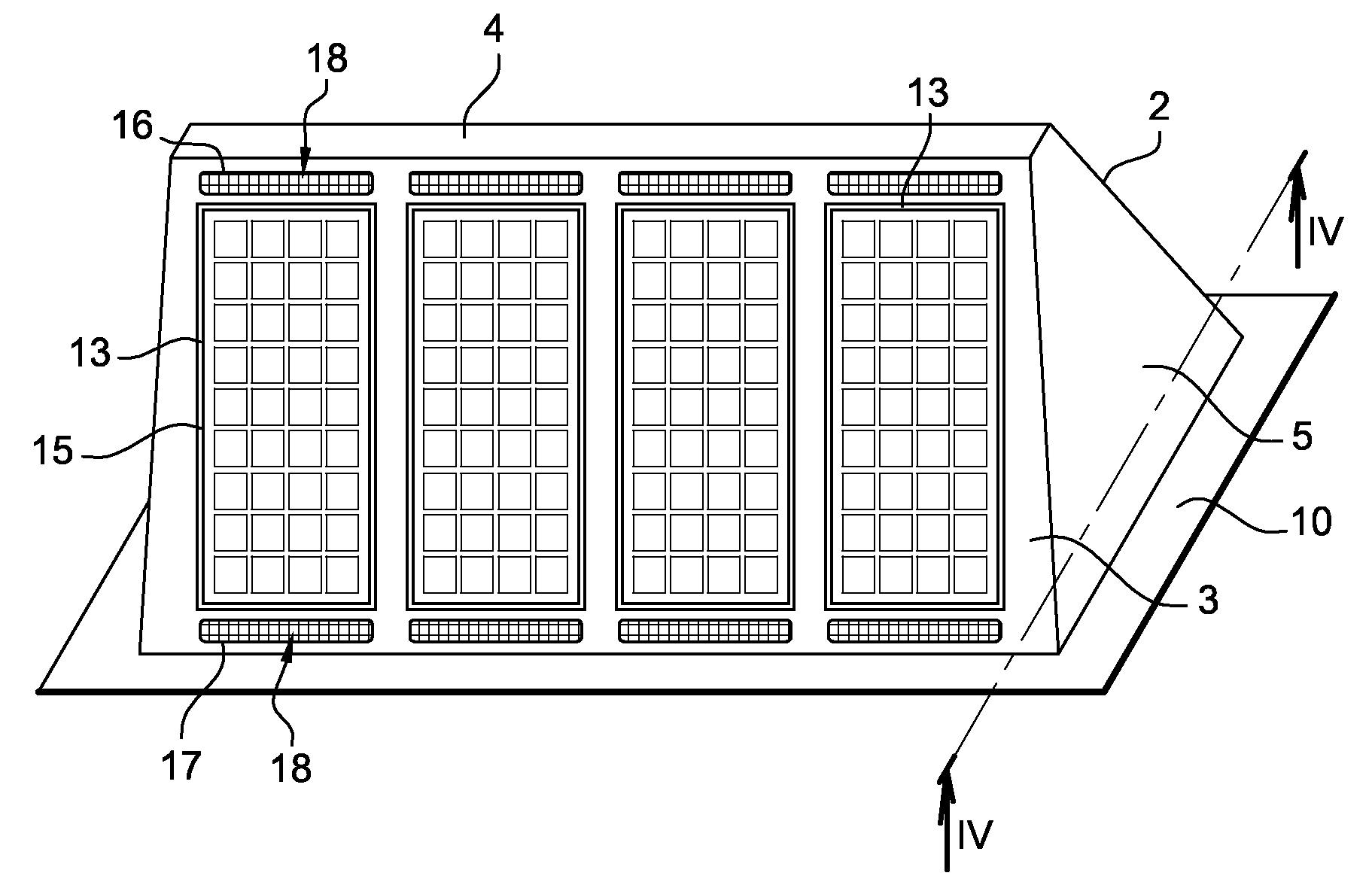
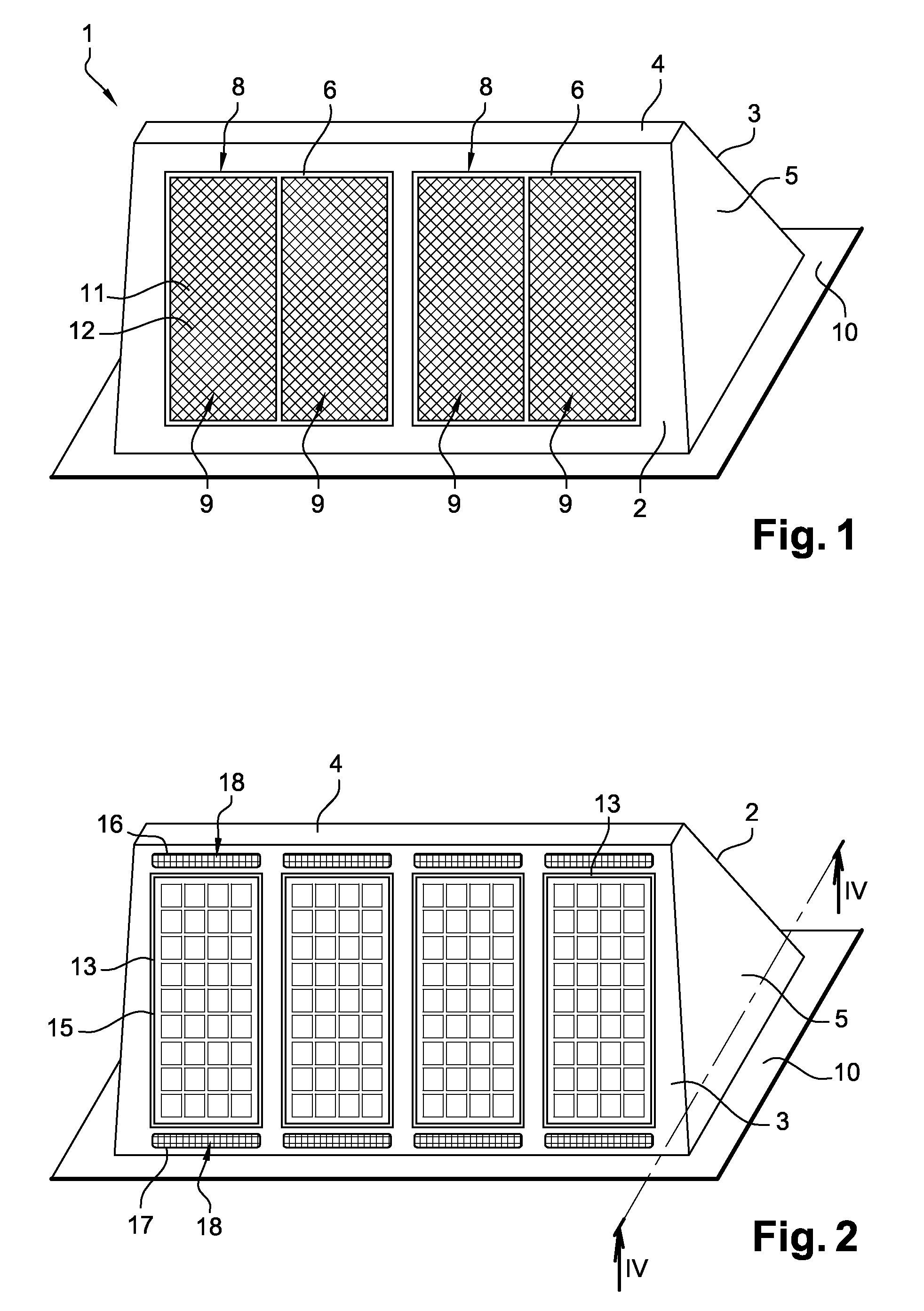
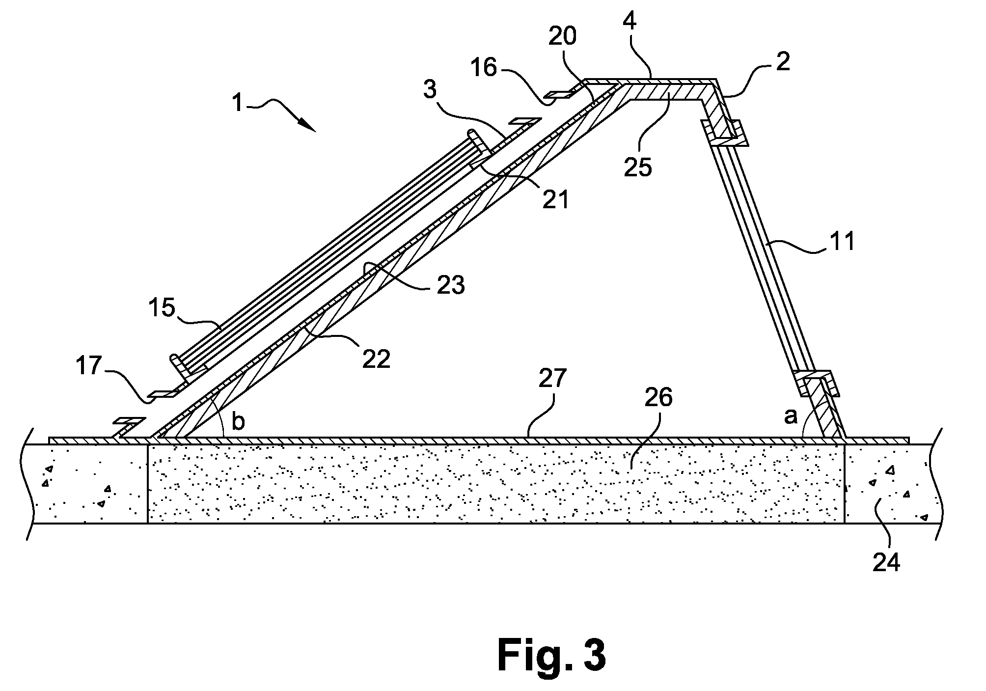
[0027]As shown in FIGS. 1 to 3, a modular construction element 1 according to the invention comprises a body having a wall formed by a first face 2 inclined to a horizontal plane, a second face 3 inclined to a horizontal plane and a strip 4. The orientation of the second face 3 is opposite that of the first face 2 so that the two faces 2, 3 have substantially the shape of an inverted V, seen in cross section perpendicular to the plane of the faces. The apex of this inverted V is truncated, the two faces being joined by the flat horizontal strip 4.

[0028]The modular element 1 also includes two lateral faces 5 placed transversely with respect to the first and second faces 2, 3 and to the strip 4.

[0029]This wall defines a downwardly open space, the edge of the downward-facing opening consisting of the lower edges of the first and second faces 2, 3 and of the lateral faces 5. The edge of the opening is surrounded by a flat outer rim 10.

[0030]As illustrated in FIG. 3, the second face 3 is...


PUM


Abstract

The invention relates to a modular construction element used to close a building roof, in particular a flat roof, comprising a first face inclined with respect to a horizontal plane, having at least one transparent or translucent portion suitable for allowing natural light to illuminate the inside of the building; a second face inclined with respect to a horizontal plane, of opposite orientation to the first face, having at least one solar panel comprising at least one photovoltaic module; and at least part of the faces of the modular element comprising at least one thermal and/or acoustic insulation layer.

Description

BACKGROUND OF THE INVENTION[0001]The invention relates to a modular construction element used to close a building roof, in particular a flat roof. The invention further relates to a roof comprising at least one modular element according to the invention.DESCRIPTION OF THE PRIOR ART[0002]Conventionally, building roofs, for example of warehouses or factories, take the form of flat roofs. In certain cases, it may happen that these roofs are closed by roofs of substantially prismatic shape, which are called shed roofs. More precisely, these roofs have translucent portions comprising glass panes arranged so as to be steeply inclined on the north side for the purpose of obtaining diffuse light inside the building, better known by the name “skylight”. Furthermore, these roofs may include a solar collector, placed for example so as to be oriented facing south, this particular orientation enabling the solar collector to be more effective. Such a roof is known in particular from document DE 2...

Claims


Application Information

Patent Timeline
Patent Type & Authority Applications(United States)
IPC IPC(8): E04D13/18
CPCF24J2/045F24J2/4614F24J2/523Y02B10/12H02S20/24Y02B10/70Y02E10/47Y02E10/50H02S20/00Y02B10/20F24S20/67F24S25/10F24S40/44Y02B10/10
Inventor PROISY, BERNARD
Owner PHOTOWATT INT
Why Eureka
Try Eureka