
Systems and methods for varying the thrust of rocket motors and engines while maintaining higher efficiency using moveable plug nozzles

Inactive Publication Date: 2009-08-27
GHKN ENG
View PDF43 Cites 22 Cited by
  • Summary
  • Abstract
  • Description
  • Claims
  • Application Information

AI Technical Summary

Benefits of technology

[0017]In consideration of the above-identified aspects of rocket design, the present invention provides systems and methods for varying the thrust of a rocket while maintaining significantly higher nozzle efficiency over the thrust range. A moveable plug design is provided for use in rocket motors and engines. The plug may be part of a “moveable plug” nozzle, where a combustion chamber exit, such as a cowl, and plug are moveable with respect to one another. A plug or combustion chamber exit may be attached, or otherwise operably coupled, to an adaptive control s

Problems solved by technology

Nuclear propulsion, using a fission reactor, a fusion reactor, or directed radioactive isotope decay, has been investigated but remains largely undeveloped.
When this occurs, the exhaust is forced inward and no longer exerts force on the nozzle walls, so thrust is decreased and the rocket becomes less efficient.
Liquid rocket engines employing efficient variable propellant flow into the combustion chamber have been used effectively for many years but have suffered from performance inefficiencies inherent in the use of cone or bell nozzles over the wide NPR range which results from the variable chamber pressure and resulting variable thrust when using a rocket engine with a fixed throat area.
While systems such as the above have improved liquid engine rocketry, no liquid rocket engine design has adequately leveraged improved techniques to provide a simple and powerful engine with both high efficiency over a wide range of backpressures and easily controlled thrust.
Nozzles with moveable pintles affect NPR in a different way, but suffer nonetheless from loss of nozzle efficiency at “off-design” NPRs.
However, because the pintle is used in combination with a cone nozzle, varying NPRs force rockets of such a design to operate at sub-optimal NPRs.
Thus, theory and test results demonstrate that the tested designs cannot maintain high performance over a wide range of NPRs.
This is largely because such designs suffer from efficiency losses due to expansion problems in a fixed nozzle exit cone or bell nozzle configuration.
Regardless of whether the change in NPR occurs because of decreasing exhaust pressure (increasing altitude) or decreasing chamber pressure (thrust throttling), nozzle efficiency suffers due to non-optimal nozzle expansion at off-design NPRs.
Performance losses of up to 30% off of optimal efficiency can occur at off-nominal NPRs.
To date, no method has been identified for maintaining near-optimal nozzle efficiency while varying thrust over a wide range.
In summary, both liquid and solid rocket motor designs have failed to realize their full potential in providing both high efficiency over a wide range of NPRs, and thrust control.

Method used


Image

  • Systems and methods for varying the thrust of rocket motors and engines while maintaining higher efficiency using moveable plug nozzles
  • Systems and methods for varying the thrust of rocket motors and engines while maintaining higher efficiency using moveable plug nozzles
  • Systems and methods for varying the thrust of rocket motors and engines while maintaining higher efficiency using moveable plug nozzles

Examples


Embodiment Construction

[0025]Certain specific details are set forth in the following description and figures to provide a thorough understanding of various embodiments of the invention. Certain well-known details often associated with the design and manufacture of rocket motors are not set forth in the following disclosure, however, to avoid unnecessarily obscuring the various embodiments of the invention. Further, those of ordinary skill in the relevant art will understand that they can practice other embodiments of the invention without one or more of the details described below. Finally, while various methods may be described with reference to steps and sequences in the following disclosure, the description as such is for providing a clear implementation of embodiments of the invention, and the steps and sequences of steps should not be taken as required to practice this invention.

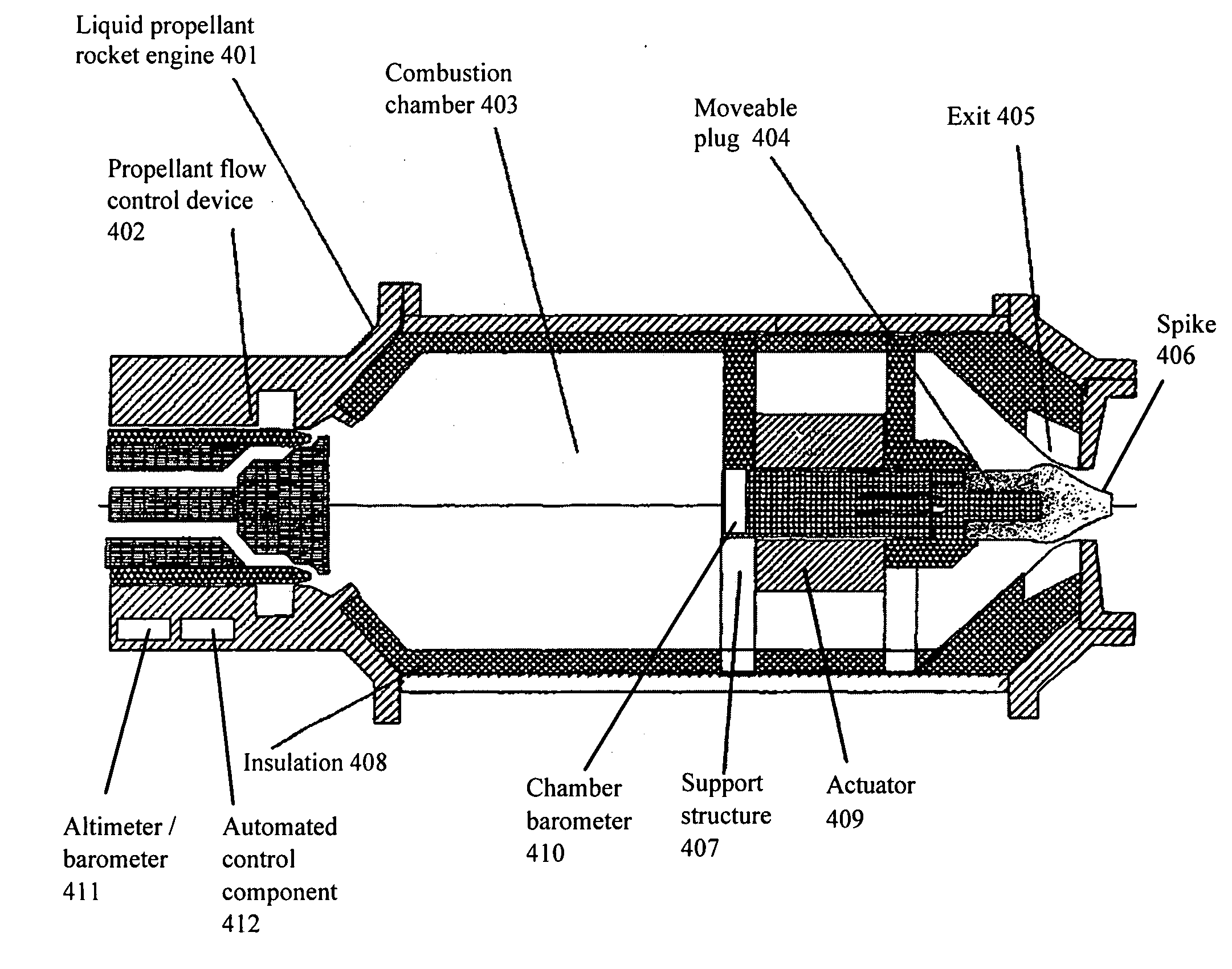
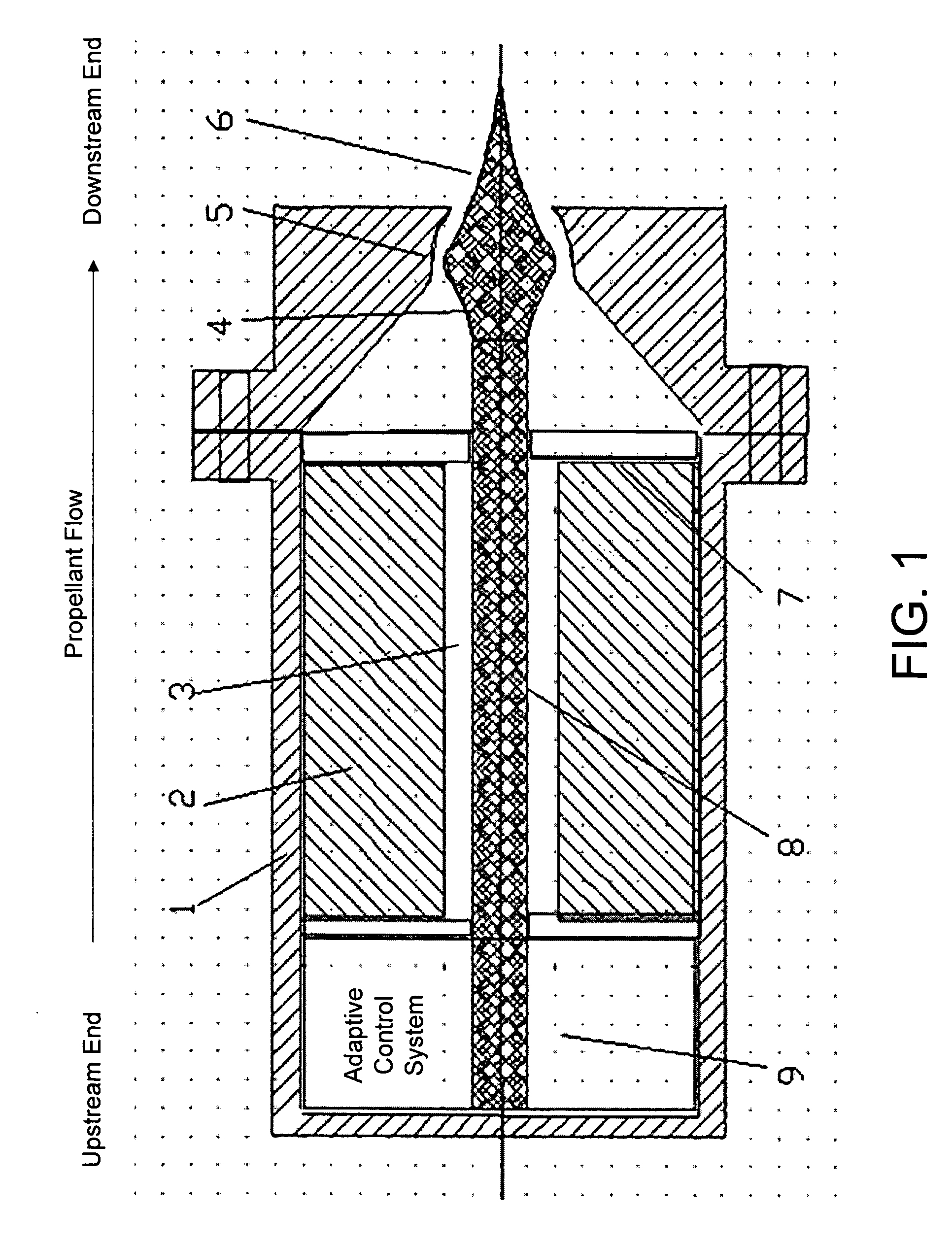
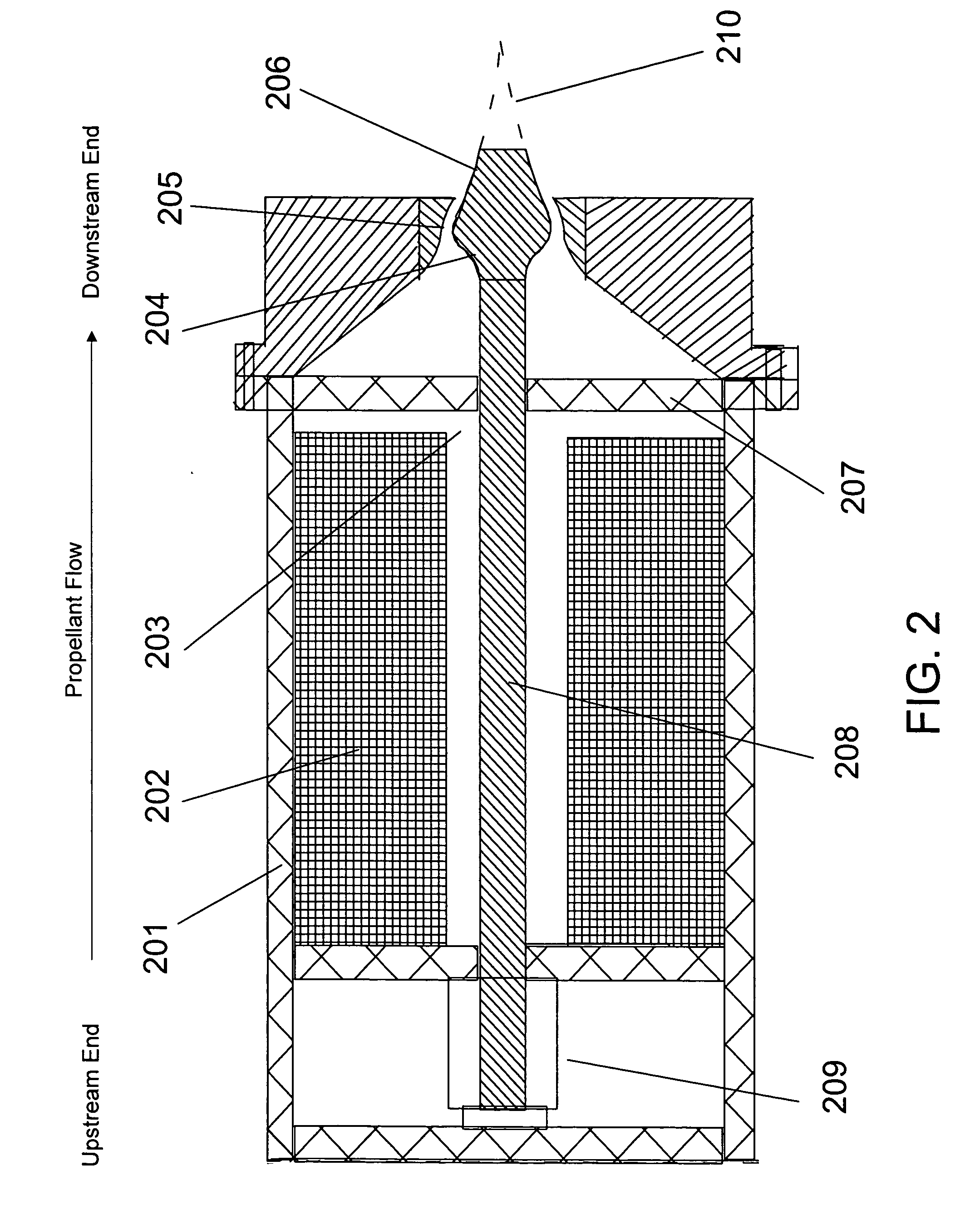
[0026]FIG. 1 demonstrates a cross-sectional view of an exemplary rocket motor 1 that employs various features for improved ...


PUM


Abstract

The thrust of a rocket motor can be varied to optimize Nozzle Pressure Ratio (NPR) using a design that allows for adjusting the relative position of a plug and a combustion chamber exit. The plug or the exit may be attached to an adaptive control system for position modification. The relative position of the plug and exit may be adjusted to optimize NPR to account for changing propellant flow and / or changing ambient pressure.

Description

FIELD OF THE INVENTION[0001]This invention relates to rocket propulsion, and more particularly to controlling the thrust of a rocket engine or rocket motor and maintaining the thrust efficiency of the system.BACKGROUND OF THE INVENTION[0002]Modern rocket propulsion systems can be classified according to the type of energy source: chemical, nuclear, and solar. Chemical rocket propulsion uses the energy from a high-pressure combustion reaction of propellant chemicals, which heats reaction product gases to very high temperatures. These gases are then expanded in a nozzle and accelerated to very high velocities, which, in turn, bring rockets to high velocities in an opposite direction. Nuclear propulsion, using a fission reactor, a fusion reactor, or directed radioactive isotope decay, has been investigated but remains largely undeveloped. Solar propulsion may use solar panels to heat a gas. The expanded gas can be expelled through an exhaust nozzle, as with chemical propulsion.[0003]Ch...

Claims


Application Information

Patent Timeline
IPC IPC(8): F02K9/86F02K9/56F02K9/62
CPCF02K9/62F02K9/86F02K9/80
Inventor NYBERG, DONALD GERRITGROUDLE, THOMAS ADRIANSMITH, RICHARD DOYLESHUBA, JOHN A.SMITH, RICHARD T.
Owner GHKN ENG
Learn More