
Systems for use with multiple safety devices and connectors for use therewith

a safety device and connector technology, applied in safety belts, sports equipment, cleaning equipment, etc., can solve the problems of inability to align with both anchor points, the drum assembly suddenly locks, and the extension of the lifeline is difficul

Active Publication Date: 2009-08-27
HONEYWELL INT INC
View PDF27 Cites 64 Cited by
  • Summary
  • Abstract
  • Description
  • Claims
  • Application Information

AI Technical Summary

Benefits of technology

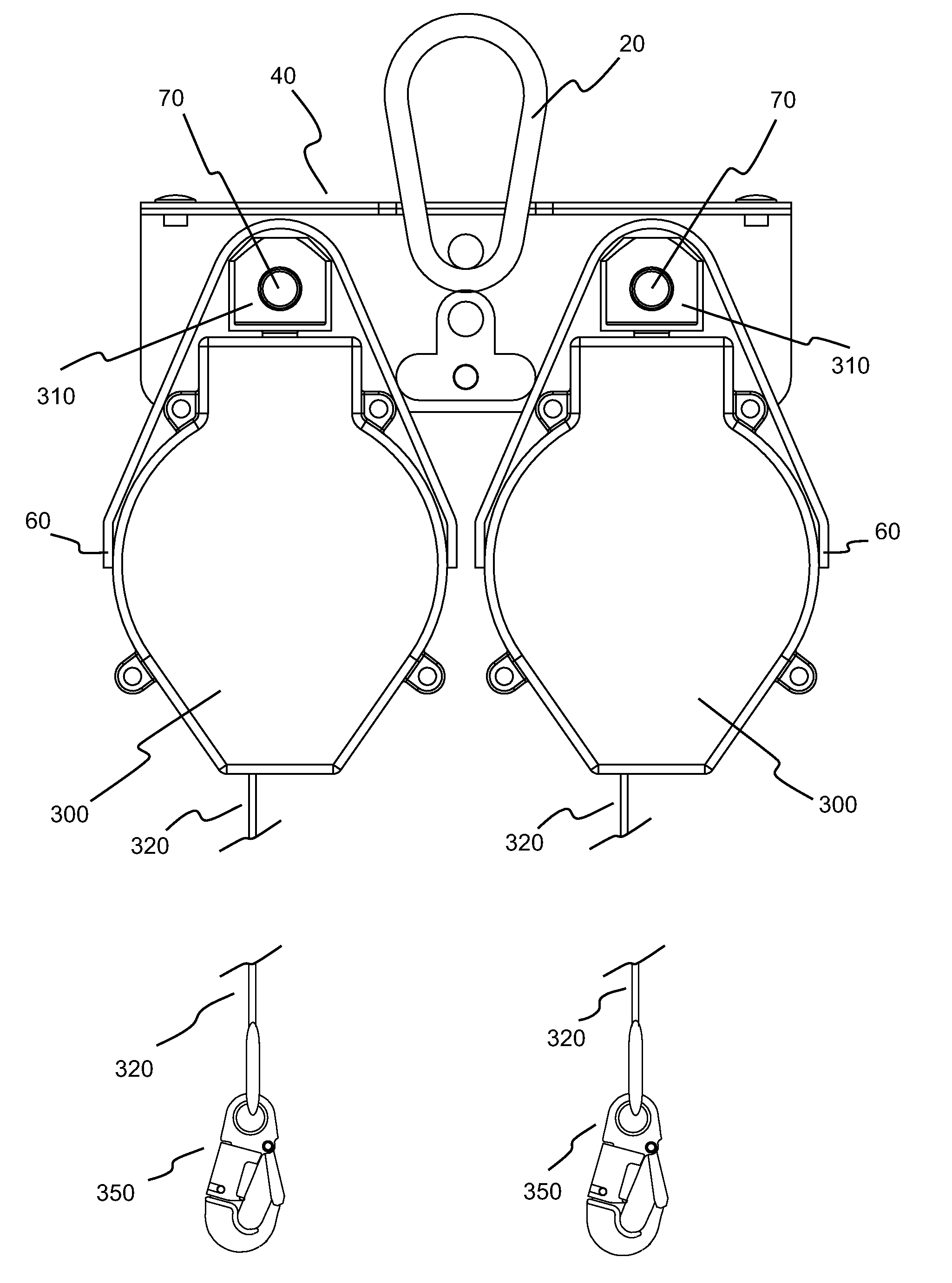
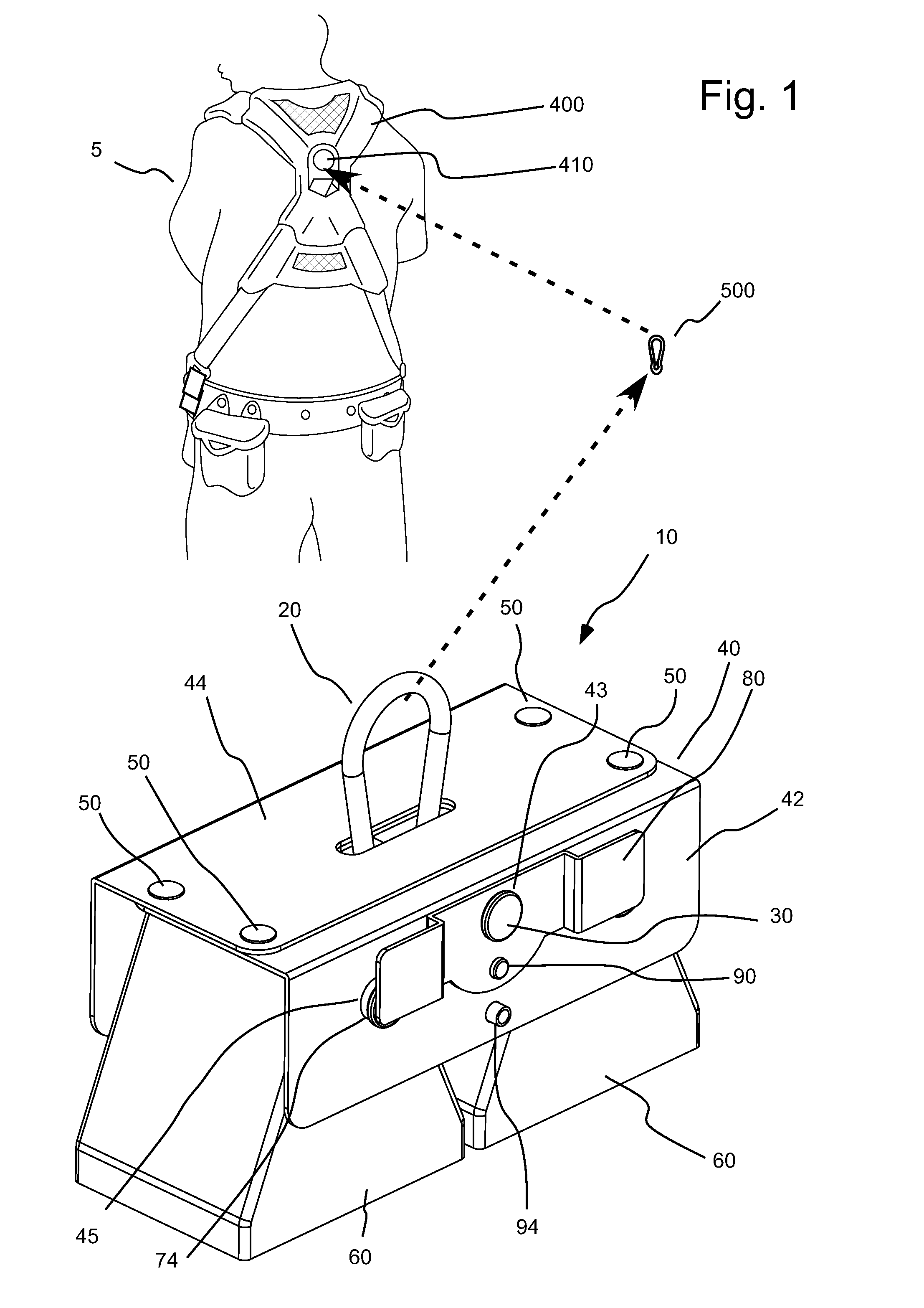
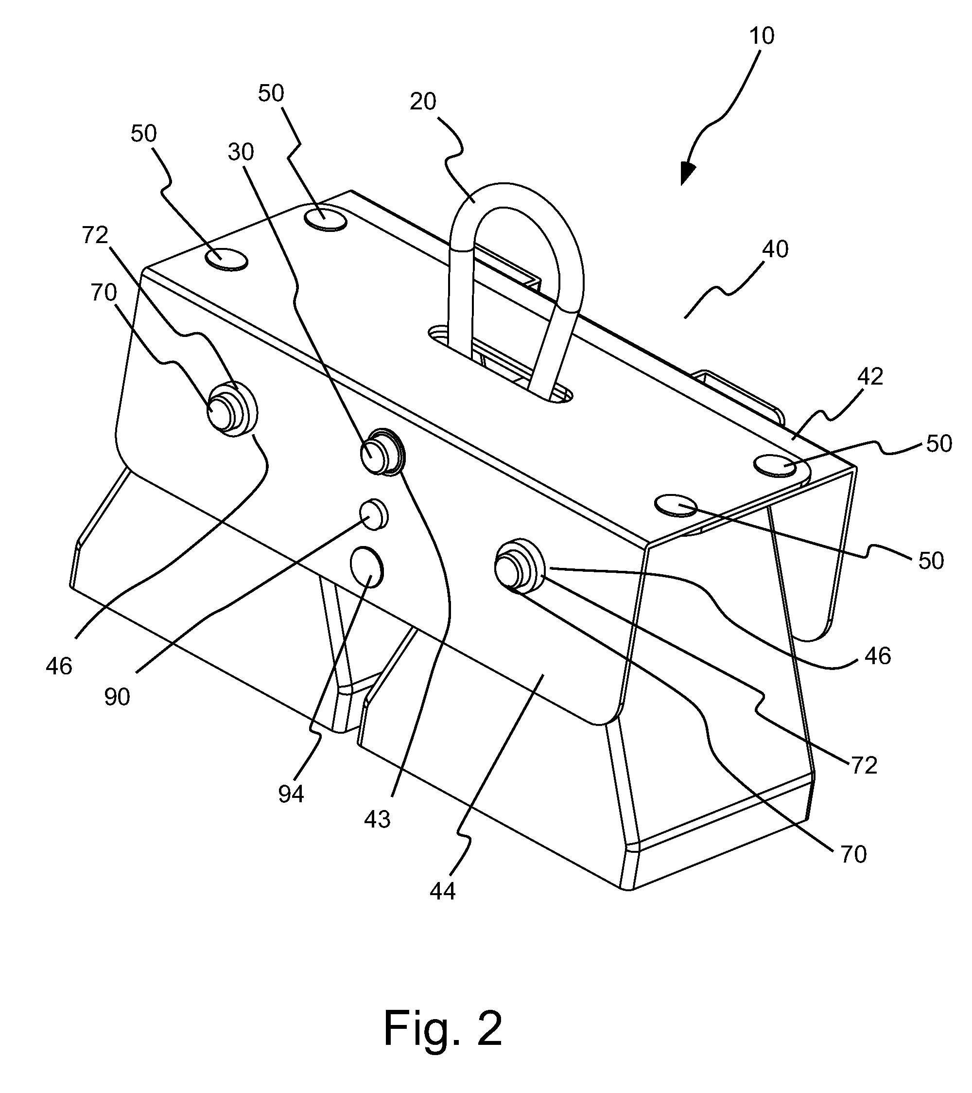
[0032]In several embodiments, the harness connector includes a third extending member or shaft extendible between the first frame member and the second frame member to connect to a connector ring attached to the harness. The third extending member can, for example, be movably connected to the frame. The third extending member can be positioned on the frame at a position intermediate between the first extending member and the second extending member and generally equidistant from the first extending member and the second extending member as described above. Such positioning can, for example, balance the weight of attached self-retracting lifelines.
[0034]In several embodiments, the connector includes a connector member that is pivotably connected to the frame on a first end thereof and is removably connected to the frame member on a second end thereof. The connector member can, for example, include an engagement member in the vicinity of the second end thereof that is operable to removably connect to a cooperating engagement member attached to the frame. The engagement member can, for example, include an extending member that engages a seating in the cooperating engagement member. The connector can further include a latch system to engage at least one of the engagement member and the cooperating engagement member to prevent disengagement of the engagement member and the cooperating engagement member when the latch system is in a closed state.

Problems solved by technology

For example, when the rope, cable or web being pulled from the self-retracting lifeline system causes the drum assembly to rotate above a certain angular velocity or experience an angular acceleration above a certain level, a brake mechanism can cause the drum assembly to suddenly lock.
However, there are a number of disadvantages associated with such a device.
For example, when a user is moving horizontally, the webbing of the lifelines makes a 90 degree bend when entering or exiting the device, making extension of the lifeline difficult.
There is, for example, often an inability to align with both anchor points during a transition form one anchor point to another.
Bends in one of the lifelines can also prevent automatic retraction of the lifeline, allowing extra slack in the lifeline, and potentially increasing the free fall distance of the user.
Additionally, if either retraction mechanism of the device becomes inoperative, the entire unit must be discarded or returned to the manufacturer for repair.
Furthermore, manufacture of such a device requires the production of specialized sets of left and right hand parts which are unique to the device, while performing the complex functions of a self retracting lifeline or SRL.
This additional distance results in an increase in fall clearance as well as the ability for the devices to become twisted or intertwined or otherwise interfere with each other.
There is also a restriction of the ability of each device to work and orient independently of each other.

Method used


Image

  • Systems for use with multiple safety devices and connectors for use therewith
  • Systems for use with multiple safety devices and connectors for use therewith
  • Systems for use with multiple safety devices and connectors for use therewith

Examples


Embodiment Construction

[0102]The devices, systems and methods of the present invention reduce or eliminate a number of problems associated with currently available systems while providing highly functional, multiple safety device (for example, multiple self-retracting lifeline) systems for use by persons performing in situations wherein there is a risk of injury from a fall.

[0103]As used herein and in the appended claims, the singular forms “a,”“an”, and “the” include plural references unless the content clearly dictates otherwise. Thus, for example, reference to “a connector” includes a plurality of such connectors and equivalents thereof known to those skilled in the art, and so forth, and reference to “the connector” is a reference to one or more such connectors and equivalents thereof known to those skilled in the art, and so forth.

[0104]FIGS. 1 through 9 illustrate one embodiment of a support system 10 of the present invention for placing multiple self-retracting lifelines 300 (see, for example, FIG....


PUM

PropertyMeasurementUnit
movementaaaaaaaaaa
range of anglesaaaaaaaaaa
areaaaaaaaaaaa

Abstract

A system includes a support including an extending rigid member and a first attachment at a first position on the rigid member to which a first self-retracting lifeline is attached. The first self-retracing lifeline includes a first housing from which a first lifeline exits. The first housing is movable relative to the rigid member. The system also includes at least a second attachment at a second position on the rigid member to which a second self-retracing lifeline. The second self-retracting lifeline includes a second housing from which a second lifeline exits. The second housing is movable relative to the rigid member independent of the movement of the first housing. The first position is spaced from the second position. The system further includes a connector attached to the frame to connect the frame to an article (for example, a safety harness such as a full body safety harness) worn by a user.

Description

CROSS-REFERENCE TO RELATED APPLICATION[0001]This application claims benefit of U.S. Provisional Patent Application Ser. No. 61 / 031,351, filed Feb. 25, 2008, and U.S. Provisional Patent Application Ser. No. 61 / 042,839, filed Apr. 7, 2008, the disclosures of which is incorporated herein by reference.BACKGROUND OF THE INVENTION[0002]The present invention relates to systems for use with multiple safety devices such as self-retractable lifeline systems or self-retracting lanyard systems and connectors for use therewith, and, particularly, to systems enabling attachment of multiple self-retracting lifelines and to connectors for attaching multiple elements to a person wearing a safety harness.[0003]The following information is provided to assist the reader to understand the invention disclosed below and the environment in which it will typically be used. The terms used herein are not intended to be limited to any particular narrow interpretation unless clearly stated otherwise in this doc...

Claims


Application Information

Patent Timeline
Patent Type & Authority Applications(United States)
IPC IPC(8): A62B35/00A62B1/08
CPCA62B35/0037Y10T24/45435Y10T29/49947A62B35/0093F16B45/027F16B45/034
Inventor SMITH, HUGHMERCIER, DOUGLASBALQUIST, ROSSMONTGOMERY, BRIANPARKER, THOMAS W.ANDERSON, PRESTON L.
Owner HONEYWELL INT INC
Learn More