Mr compatible rotating anode x-ray tube

a technology of rotating anodes and x-ray tubes, which is applied in the field of magnetic resonance imaging, can solve the problems of less than 1% of the electron beam energy being converted and a tremendous amount of heat being deposited on the anod

Active Publication Date: 2009-08-27
THE BOARD OF TRUSTEES OF THE LELAND STANFORD JUNIOR UNIV
View PDF6 Cites 3 Cited by
  • Summary
  • Abstract
  • Description
  • Claims
  • Application Information

AI Technical Summary

Problems solved by technology

Due to the inefficiency of this process, less than 1% of the electron beam energy is converted to x-ray energy; a tremendous amount of heat is deposited on the anode.

Method used


Image

  • Mr compatible rotating anode x-ray tube
  • Mr compatible rotating anode x-ray tube
  • Mr compatible rotating anode x-ray tube

Examples


Embodiment Construction

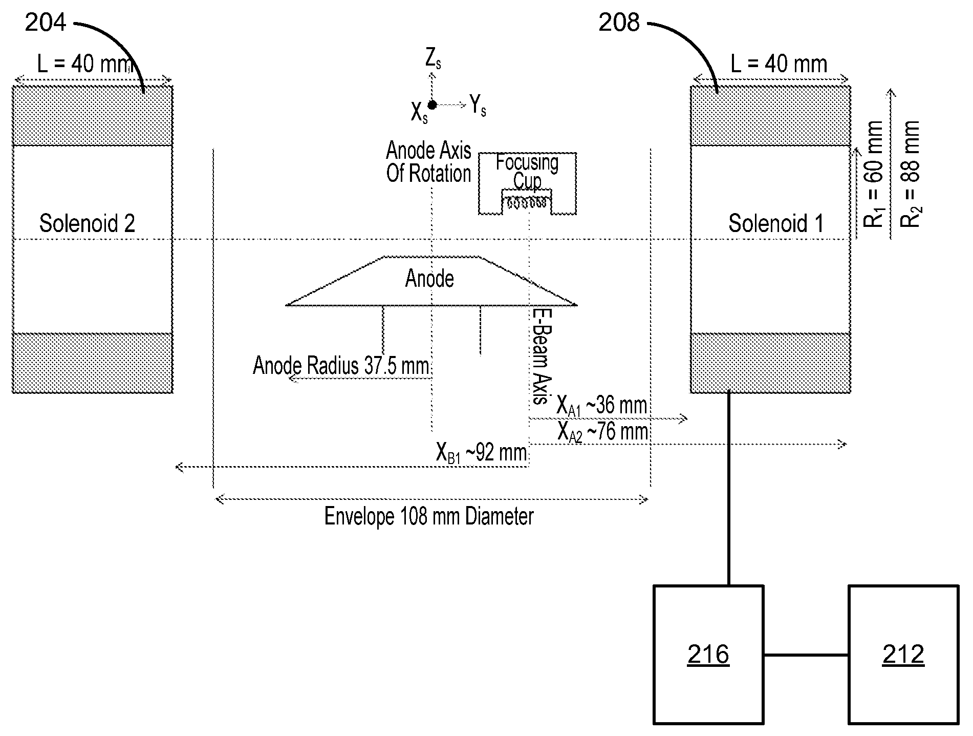
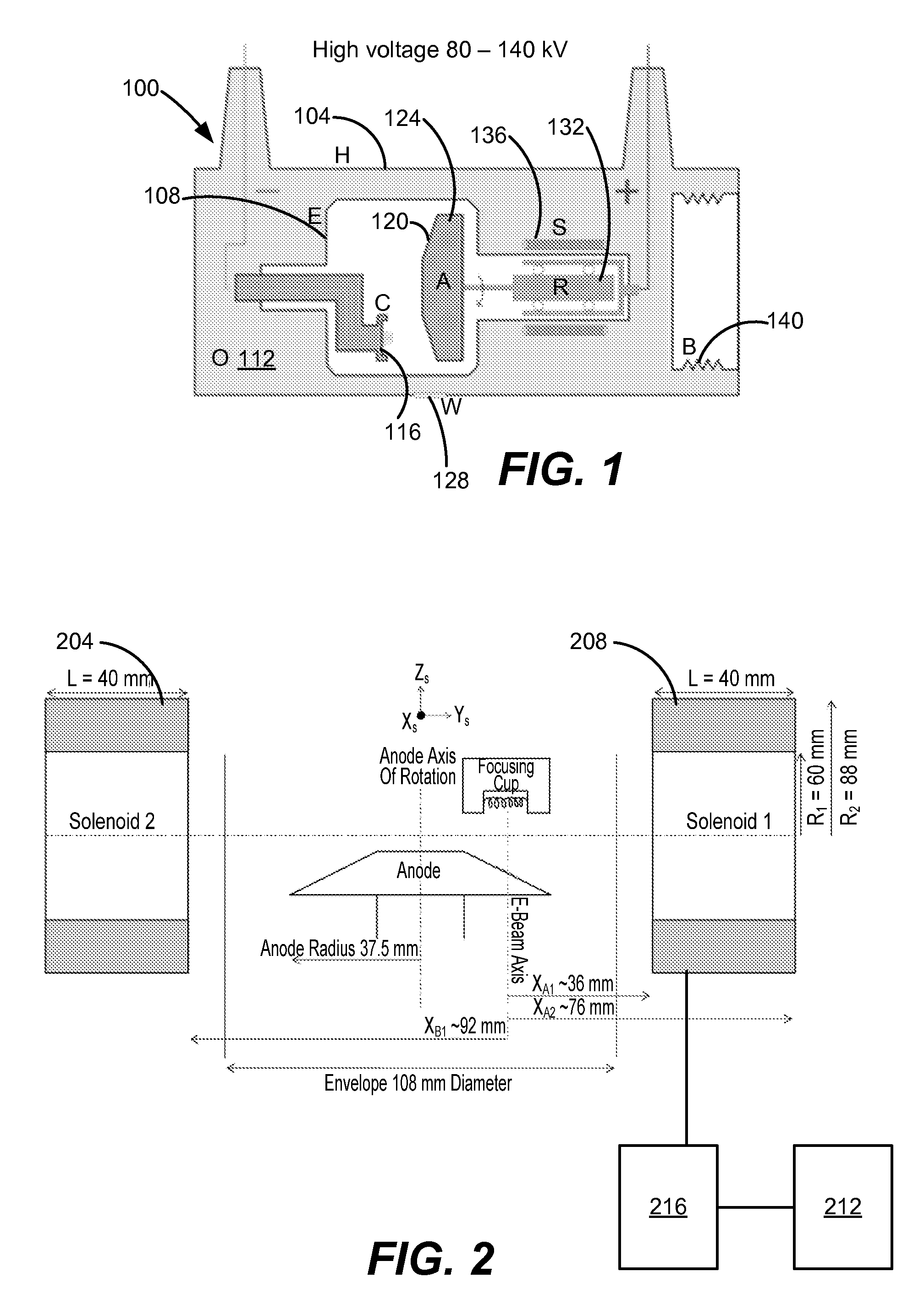
[0020]When placing the device shown in FIG. 1 in an MR fringe field, two major concerns arise; the positioning, size, and shape of the focal spot on the anode and the operation of the induction motor used to turn the anode. Any external magnetic field will alter the motion of the electrons during their transit from the cathode to the anode. The exact nature of the electron beam deflection will depend upon the external field strength and direction. The highest fields expected in this position of the tube will be the radial fringe fields (˜1000 gauss), which will be along the axis of the tungsten filaments. These radial fields could lead to electron beam deflections on the order of 15 mm, exceeding the operating parameters if not corrected for.

[0021]When an induction motor is operating in the presence of an external magnetic field, the stator soft iron ring becomes partially magnetized by the external field, in addition to the magnetization produced by the stator coils. These effects ...


PUM


Abstract

An apparatus for use in a magnetic resonance (MR) system, which generates an external MR magnetic field, is provided. A rotor comprises a rotor shaft with an axis along a length of the rotor shaft and a plurality of coils on the rotor shaft. A housing supports and surrounds the rotor, where a part of the housing surrounds sides of the rotor and where the part of the housing surrounding sides of the rotor is magnet free. A mount allows for the mounting of the housing to the MR system in a location where the MR system provides a magnetic field, wherein a component of the MR magnetic field that is perpendicular to the axis of the rotor shaft is at least 100 Gauss. An active timer applies a voltage to the plurality of coils with alternating polarity. Contacts provide an electrical connection between the active timer and the plurality of coils.

Description

BACKGROUND OF THE INVENTION[0001]This invention relates generally to magnetic resonance imaging (MRI). More specifically, the invention relates to a rotating anode x-ray tube for MRI.[0002]A simplified diagram of a rotating anode x-ray tube used in the prior art is shown in FIG. 1. The rotating anode x-ray tube 100 comprises a housing 104, a glass envelope 108 for maintaining a vacuum around the cathode and anode, insulating oil 112, a cathode and focusing cup 116, a target 120, an anode 124, an x-ray window 128, a rotor 132, a stator 136, and expansion bellows 140. During conventional use the tungsten wire filaments held in the focusing cup are heated to ˜2200° C. causing electrons to be boiled off the wire surface by the process of thermionic emission. The large potential difference (on the order of 100 kV) between the cathode and anode causes the high-energy electrons that are boiled off the tungsten wire to accelerate towards and bombard the anode creating x-rays. Due to the ine...

Claims


Application Information

Patent Timeline
Patent Type & Authority Applications(United States)
IPC IPC(8): G01R33/38
CPCG01R33/381G01R33/4812
Inventor LILLANEY, PRASHEELFAHRIG, REBECCAGANGULY, ARUNDHUTIPELC, NORBERT J.
Owner THE BOARD OF TRUSTEES OF THE LELAND STANFORD JUNIOR UNIV
Why Eureka
Try Eureka