Distributed iterative multimodal sensor fusion method for improved collaborative localization and navigation

a multimodal sensor and fusion method technology, applied in direction finders, instruments, etc., can solve the problems of inability to meet the infrastructure requirements of techniques, weak gps signals, and inability to locate people/navigable vehicles, and achieve the effect of improving position accuracy

Active Publication Date: 2009-08-27
SRI INTERNATIONAL
View PDF79 Cites 53 Cited by
  • Summary
  • Abstract
  • Description
  • Claims
  • Application Information

AI Technical Summary

Benefits of technology

[0018]A node's position accuracy may improve by a factor of √{square root over (n)} when it collaborates as part

Problems solved by technology

Unfortunately, GPS may be unavailable in several situations where the GPS signals become weak, corrupted, or non-existent.
Unfortunately, this technique has strict infrastructure requirements, requiring at least three anchor nodes for a 2D position and four anchor nodes for a 3D position.
The technique is further complicated by being heavily dependent on relative node geometry and suffers from accuracy errors due to RF propagation complexities.
There are two disadvantages for such approaches: (i) anchor nodes are an infrastructure that is inconvenient in certain applications, like soldiers behind enemy lines; (ii) estimation ambiguities such as translation, orientation, and flip exist for a network without enough anchor nodes.
Ambiguities can be eliminated by deploying a sufficient number of anchor nodes in a mobile sensor network, but this incurs the increased infrastructure costs of having to deploy multiple anchor nodes.
Highly accurate INUs are typically expensive, bulky, heavy, power-intensive, and may place limitation

Method used


Image

  • Distributed iterative multimodal sensor fusion method for improved collaborative localization and navigation
  • Distributed iterative multimodal sensor fusion method for improved collaborative localization and navigation
  • Distributed iterative multimodal sensor fusion method for improved collaborative localization and navigation

Examples


Embodiment Construction

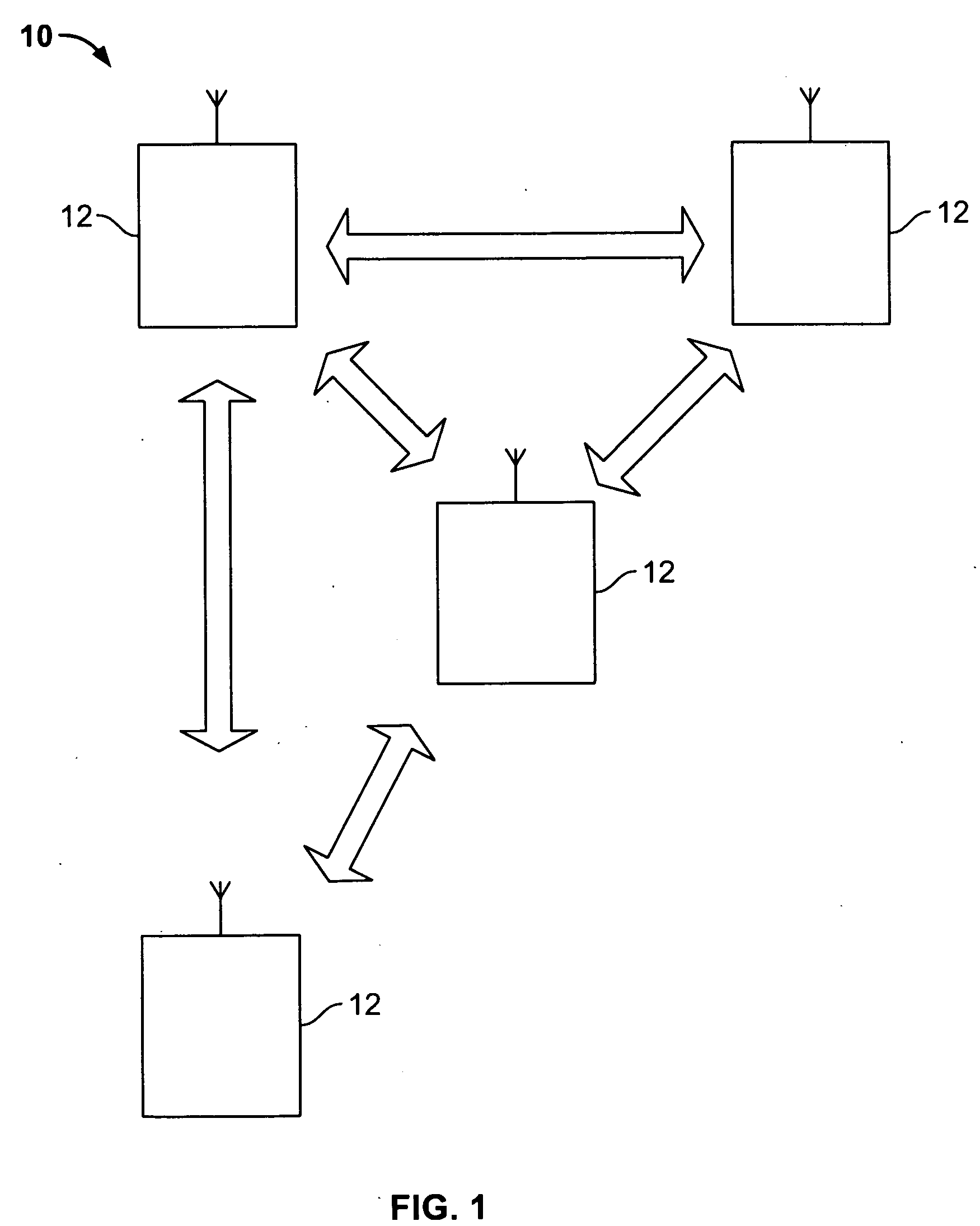
[0031]Referring now to FIG. 1, a navigation system for determining the position of at least one node in GPS-denied environments is depicted, constructed in accordance with an embodiment of the present invention, generally indicated at 10. The system 10 includes an n-node sensor network comprising a plurality of nodes 12 (people, objects, navigable entities) which communicated with each other wirelessly. In a preferred embodiment, there is no one central node. Each of the nodes 12 determines its own position by means of local position measurement devices and by means of obtaining range measurements between each node 12 and its nearest neighbors(s). Range measurements to neighboring nodes 12 may be obtained by on-board ranging equipment and by receiving / exchanging position measurements wirelessly with neighboring nodes 12. Individual local inertial navigation units (INUs), being subject to drift error, have their position measurements constrained using the exchanged radio frequency (R...


PUM


Abstract

A computer implemented method for fusing position and range measurements to determine the position of at least one node of a plurality of distributed nodes is disclosed. The method includes (a) measuring the position of at least one node; (b) computing an estimate of the position of the at least one node based on the measured position using a filter that takes account of past estimates of position; (c) receiving an estimate of position of at least a second node; (d) measuring inter-node range to the at least a second node; (e) combining the measured inter-node range with the estimate of position of at least a second node using a second filter that takes account of past estimates of position to generate a refined estimate of the position of the at least one node; and (f) when a change in the position of the at least one node is above a predetermined threshold value, setting the refined estimate of the position of the at least one node to the estimate of the position of the at least one node and repeating (c), (e), and (f).

Description

CROSS-REFERENCE TO RELATED APPLICATIONS[0001]This application claims the benefit of U.S. provisional patent application No. 61 / 015,248 filed Dec. 20, 2007, the disclosure of which is incorporated herein by reference in its entirety.GOVERNMENT RIGHTS IN THIS INVENTION[0002]This invention was made with U.S. government support under contract number N00014-06-C-0489. The U.S. government has certain rights in this invention.FIELD OF THE INVENTION[0003]The present invention relates generally to navigation systems, and more particularly, to a method and apparatus for locating people / navigable vehicles by fusing inertial and range sensor observations in a GPS denied environment.BACKGROUND OF THE INVENTION[0004]It is desirable in many applications to estimate absolute and relative 3-D position and orientation for people and objects using low-cost, small size, weight and form-factor navigation devices. In recent times, the Global Positioning System (GPS) for military and civilian applications...

Claims


Application Information

Patent Timeline
IPC IPC(8): G01S13/50
CPCG01S5/0278G01S2013/466G01S5/0294G01S5/0289
Inventor WU, SHUNGUANGMAU, SUIN-CHUONKABA, JAMESZHAO, TAO
Owner SRI INTERNATIONAL
Why Eureka
Try Eureka