
Composite Transducer for Downhole Ultrasonic Imaging and Caliper Measurement

a technology of ultrasonic imaging and caliper measurement, which is applied in the field of downhole acoustic logging tools, can solve the problems of high acoustic attenuation coefficient of certain types of drilling fluid such as heavily-weighted oil-based muds, and attenuation of acoustic energy

Active Publication Date: 2009-08-27
BAKER HUGHES INC
View PDF14 Cites 35 Cited by
  • Summary
  • Abstract
  • Description
  • Claims
  • Application Information

AI Technical Summary

Problems solved by technology

In the normal course of events, the borehole fluid is contaminated by drill cuttings, air bubbles and foreign matter which severely attenuate the acoustic energy by scattering because the physical dimensions of the contaminants are comparable to the wavelength of the wavefields emitted by the transducer.
What is even more troublesome, however, is the complication that the acoustic attenuation coefficient in certain types of drilling fluid such as heavily-weighted oil-based muds is very high, on the order of 5 dB / cm.
Even that short path length may result in an attenuation of 20 dB.
Although it is true that the coefficient of attenuation diminishes with decreasing acoustic frequency, space considerations and resolution requirements do not permit the use of large, low-frequency transducers.

Method used


Image

  • Composite Transducer for Downhole Ultrasonic Imaging and Caliper Measurement
  • Composite Transducer for Downhole Ultrasonic Imaging and Caliper Measurement
  • Composite Transducer for Downhole Ultrasonic Imaging and Caliper Measurement

Examples


Embodiment Construction

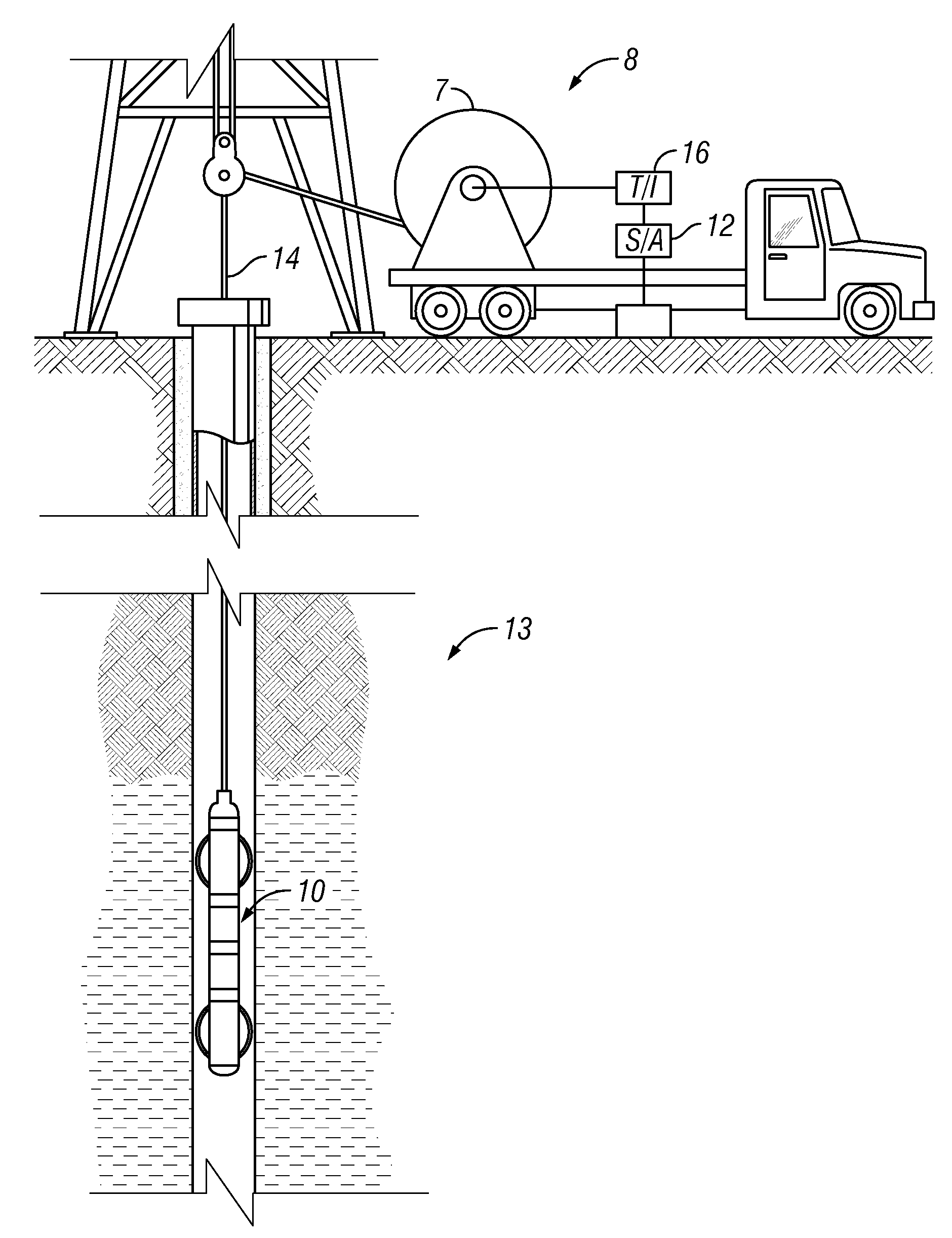
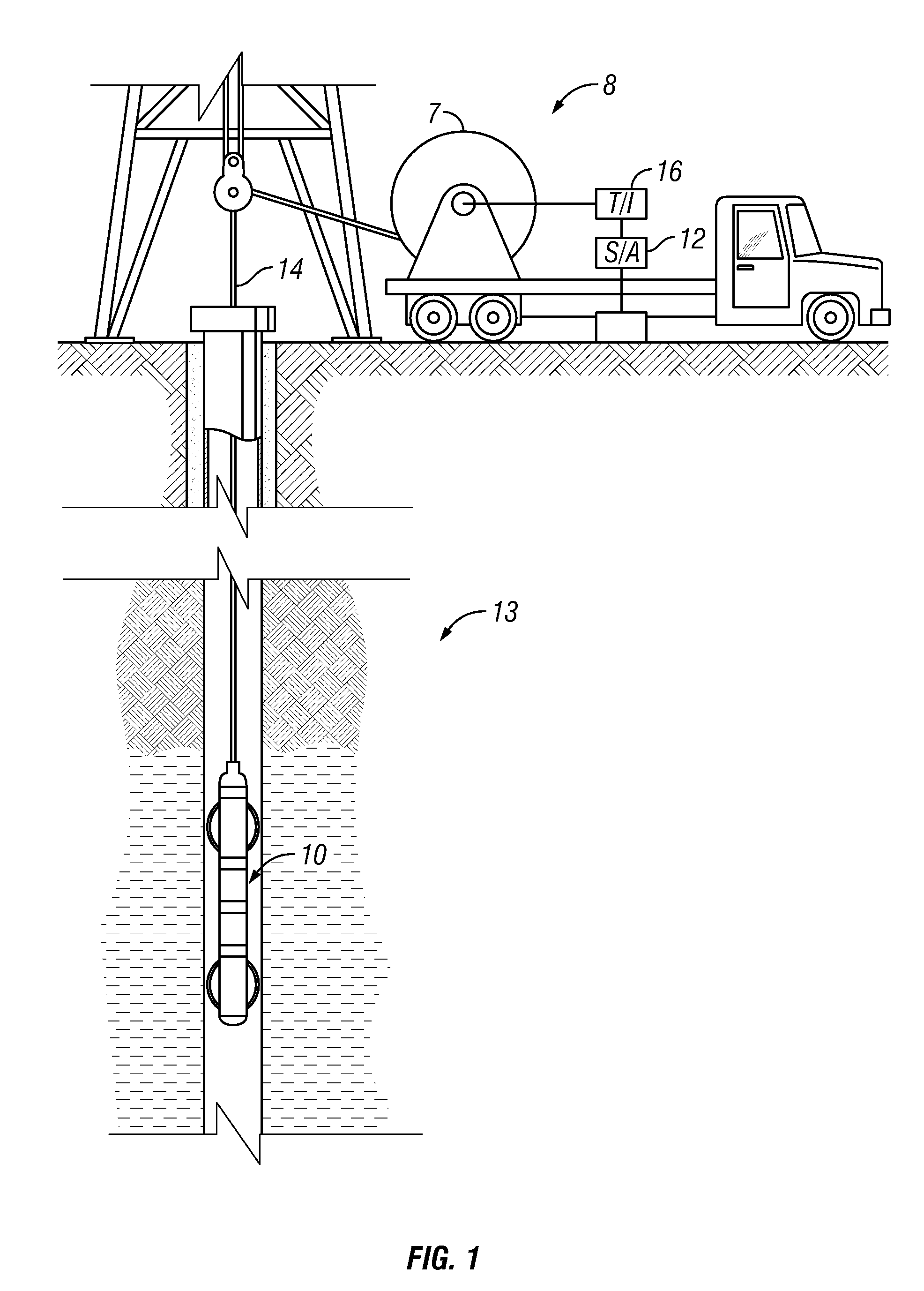
[0019]Referring to FIG. 1, a well logging instrument 10 is shown being lowered into a wellbore 2 penetrating earth formations 13. The instrument 10 can be lowered into the wellbore 2 and withdrawn therefrom by an armored electrical cable 14. The cable 14 can be spooled by a winch 7 or similar device known in the art. The cable 14 is electrically connected to a surface recording system 8 of a type known in the art which can include a signal decoding and interpretation unit 16 and a recording unit 12. Signals transmitted by the logging instrument 10 along the cable 14 can be decoded, interpreted, recorded and processed by the respective units in the surface system 8.

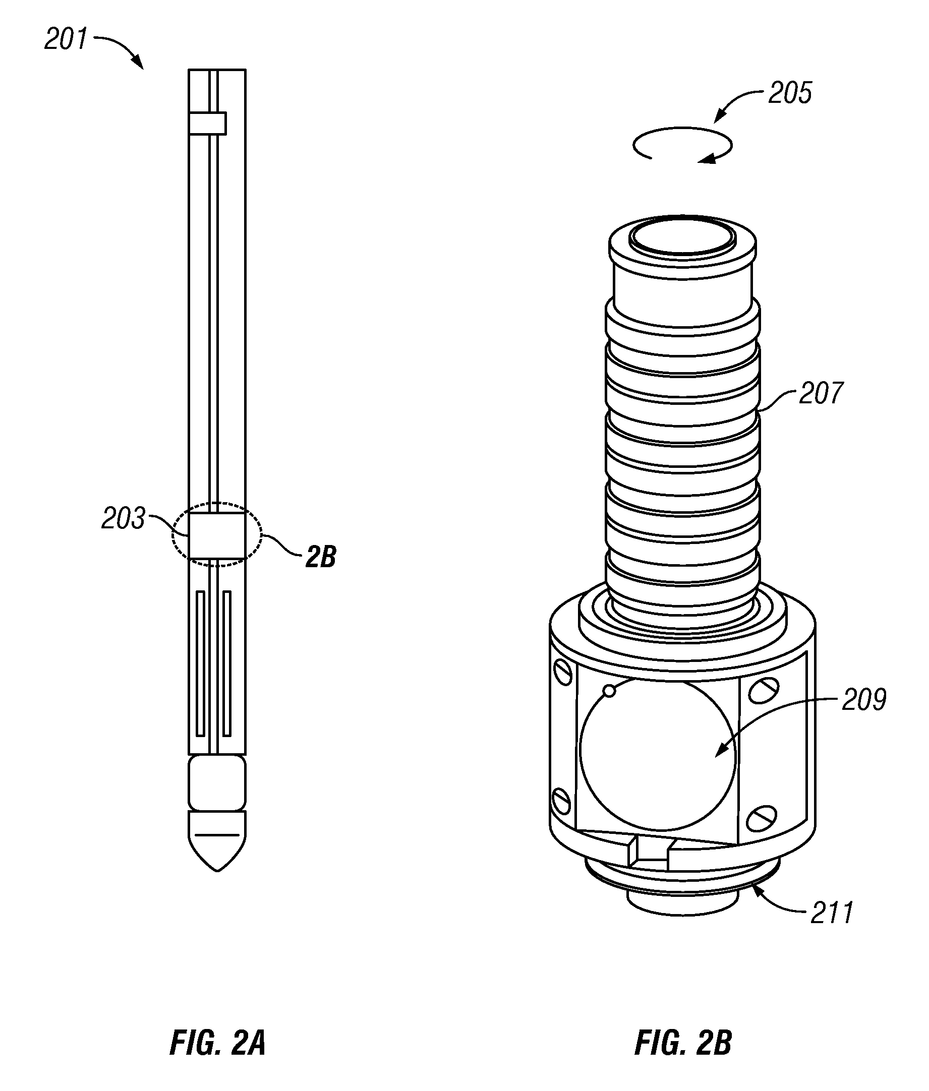
[0020]FIG. 2A shows mandrel section 201 of the imager instrument with a Teflon® window 203. Shown in FIG. 2B is the rotating platform 205 with the ultrasonic transducer assembly 209. The rotating platform is also provided with a magnetometer 211 to make measurements of the orientation of the platform and the ultrasonic tra...


PUM


Abstract

A transducer assembly for downhole imaging includes a 1-3 Piezoelectric composite transducer of high Q ceramic rods in a polymer matrix. The assembly also includes a Teflon® window, a fluid-filled cavity adjacent to the window, and impedance matching material between the composite transducer and the fluid. The transducer is positioned to reduce the reverberation time.

Description

CROSS-REFERENCES TO RELATED APPLICATIONS[0001]This application claims priority from U.S. Provisional Patent Application Ser. No. 61 / 032,007 filed on Feb. 27, 2008.FIELD OF THE PRESENT DISCLOSURE[0002]A downhole acoustic logging tool is provided for imaging the texture and structure of the borehole sidewall. The level of the acoustic signals reflected from the wall is enhanced by using a composite transducer in a borehole with highly attenuating borehole fluids.BACKGROUND OF THE PRESENT DISCLOSURE[0003]Typical acoustic logging tools may include, by way of example, a circumferential televiewer which comprises a rotating ultrasonic acoustic transducer that operates in a frequency range on the order of 100 kHz or more. Higher acoustic frequencies are preferred in order to achieve better resolution in the confined space of a borehole. In operation, the televiewer rotates at a desired rate such as 5 to 16 rotations per second to continuously scan the borehole sidewall as the televiewer is...

Claims


Application Information

Patent Timeline
IPC IPC(8): G01V1/40G01V1/52G01V1/16B06B1/06
CPCG01V1/40B06B1/0629G01V1/52B06B1/06
Inventor STEINSIEK, ROGER R.PATTERSON, DOUGLAS J.REDDING, CHARLES E.ACHANTA, ANJANI R.
Owner BAKER HUGHES INC
Learn More