
Optical network monitoring using amplifier modeling

a technology of amplifier modeling and optical network monitoring, applied in the direction of transmission monitoring, transmission monitoring/testing/fault-measurement system, electrical equipment, etc., can solve the problems of insufficient diagnosis of faults associated with underlying hardware, service provider incurring significant operational costs for network outages, and failure to occur, so as to reduce network operation and deployment costs, network operation is robust

Inactive Publication Date: 2009-08-27
LUCENT TECH INC
View PDF5 Cites 13 Cited by
  • Summary
  • Abstract
  • Description
  • Claims
  • Application Information

AI Technical Summary

Benefits of technology

[0008]Example embodiments seek to monitor optical networks, for example methods to estimate when a network is masking impairments and to determine the location and nature of these impairments, thus leading to robust network operation and reduced costs for network operation and deployment. Example embodiments may also have application to initial system development and debugging.

Problems solved by technology

However, although the self-compensating nature of the control algorithms ensures that they will strive to reach desired network performance levels, they can also mask network impairments due to, for example, hardware failures, software bugs, incorrectly installed hardware, and hardware-specific provisioning parameters used in control algorithms, e.g. fiber type, fiber length, etc.
Due to the distributed nature of the network, the failure may occur at a point in the network separated by many network elements (and a large physical distance) from the location of the impairment.
Therefore, a service provider may incur significant operational costs for network outages and in localizing the fault for repair.
Existing network management solutions focus primarily on the former, and hence are expected to be inadequate at diagnosing faults associated with the underlying hardware.

Method used


Image

  • Optical network monitoring using amplifier modeling
  • Optical network monitoring using amplifier modeling
  • Optical network monitoring using amplifier modeling

Examples


Embodiment Construction

[0018]Various example embodiments will now be described more fully with reference to the accompanying drawings in which some example embodiments are illustrated.

[0019]Detailed illustrative embodiments are disclosed herein. However, specific structural and functional details disclosed herein are merely representative for purposes of describing example embodiments. This invention may also be embodied in many alternate forms and should not be construed as limited to only example embodiments set forth herein.

[0020]Accordingly, while example embodiments are capable of various modifications and alternative forms, embodiments thereof are shown by way of example in the drawings and will herein be described in detail. It should be understood, however, that there is no intent to limit example embodiments to the particular forms disclosed, but on the contrary, example embodiments are to cover all modifications, equivalents, and alternatives falling within the scope of the invention. Like numbe...


PUM


Abstract

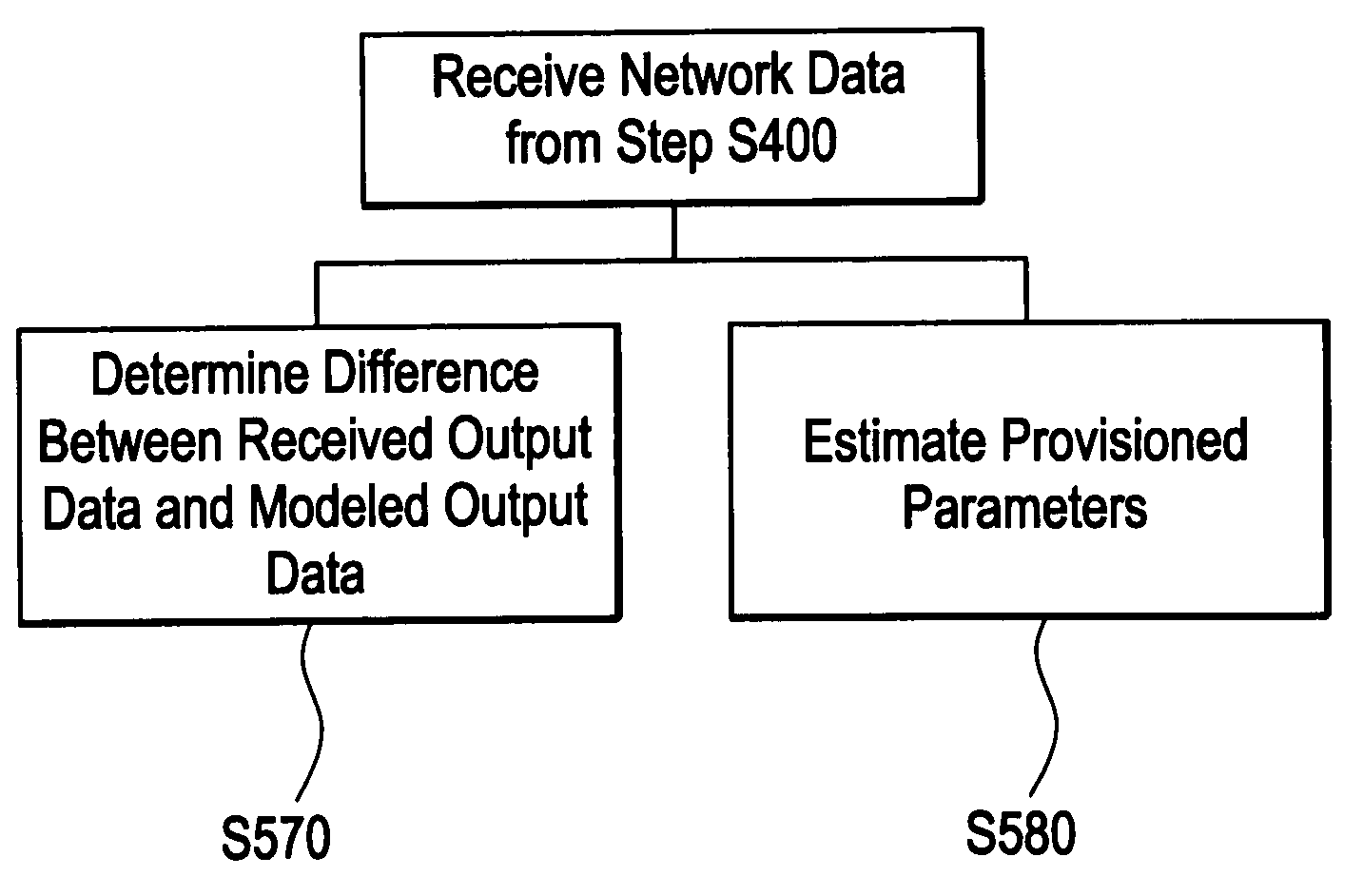
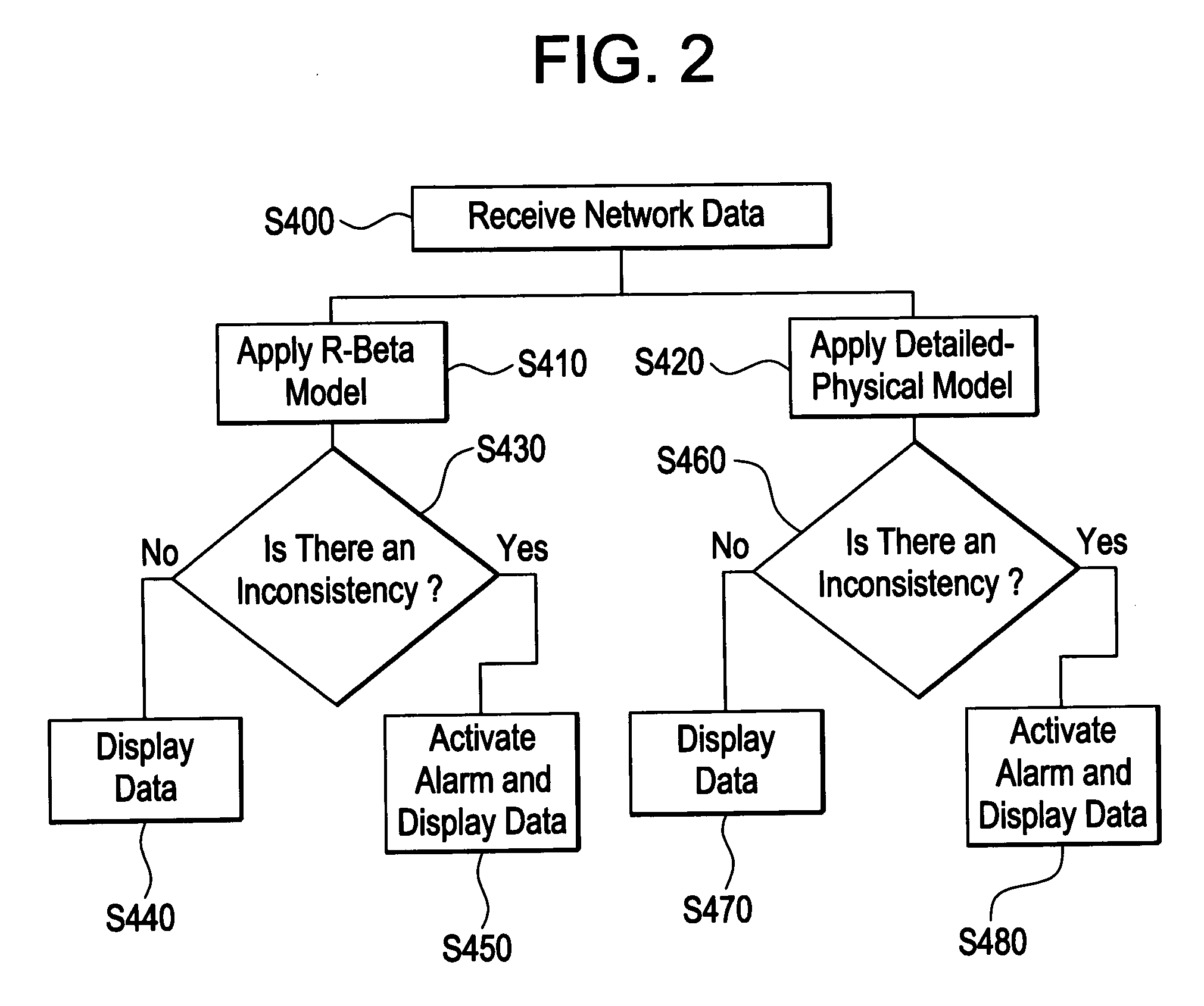
Example embodiments include a method for monitoring an optical network. The method provides received network data to a network model, which determines if there is an inconsistency within the optical network. The network models include a statistical model and a detailed-physical model, both of which model amplifier physics.

Description

BACKGROUND[0001]Optically transparent mesh networks are large, complex networks having many spans of optical fiber and may use dense wavelength division multiplexing (DWDM). Signal power levels in the optical channels in these networks are adjusted on a periodic basis by sophisticated control schemes that attempt to meet pre-defined power targets specified by a set of design and engineering rules. Signal and channel are used interchangeably throughout the disclosure. These control schemes also compensate for power disturbances due to environmental changes, adding and / or dropping of channels in the network, aging of various optical components, and other factors beyond a service provider's control.[0002]Optical networks may be designed to ensure that the channel power levels fall within certain desirable ranges as the channels propagate through the network. Typically, each channel in the system will have a target power. This is to minimize effects such as noise, which will dominate if...

Claims


Application Information

Patent Timeline
IPC IPC(8): H04B10/08
CPCH04B10/0793H04J14/0221H04B10/0797
Inventor BENGTSSON, THOMASHO, TIN KAMSALAMON, TODD R.WHITE, CHRISTOPHER A.
Owner LUCENT TECH INC
Learn More