
Gear and differential apparatus provided therewith for vehicle

a technology of differential apparatus and gear, which is applied in the direction of gearing details, gearing equipment, gearing, etc., can solve the problems of large apparatus, high total cost of the apparatus, and weak mechanical strength of the second pinion gear according to the torsion torque generated at the step portion. achieve the effect of sufficient mechanical strength

Active Publication Date: 2009-08-27
JTEKT CORP
View PDF15 Cites 19 Cited by
  • Summary
  • Abstract
  • Description
  • Claims
  • Application Information

AI Technical Summary

Benefits of technology

[0016]In view of the previously mentioned circumstances, it is an object of the present invention to provide a gear obtaining a sufficient mechanical strength against any torsion torque and to provide a differential apparatus for a vehicle with the gear preventing from being large and heavy as a whole and preventing from making a high manufacturing cost.
[0017]It is second object of the present invention to provide a differential apparatus for a vehicle with a gear performing balanced differential speed ratio and torque distributing performance to be able to be disposed not only between the front and rear tire shafts but also between the right and left tire shafts.
[0018]In order to achieve the above and other objects, one feature of the present invention provides a gear comprising a large and a small gear portions each of which pitch diameter is different respectively and each of which tooth number is same respectively and a tooth lead and a tooth space formed to be shared by the large and the small gear portions continuously from the large gear portion to the small gear portion. Thereby, since there are no step or neck portion between two gear portions of the second pinion gear as the previous second pinion gear in the prior art of the differential apparatus for the vehicle has, the gear according to the present invention can obtain a sufficient mechanical strength against any torsion torque.
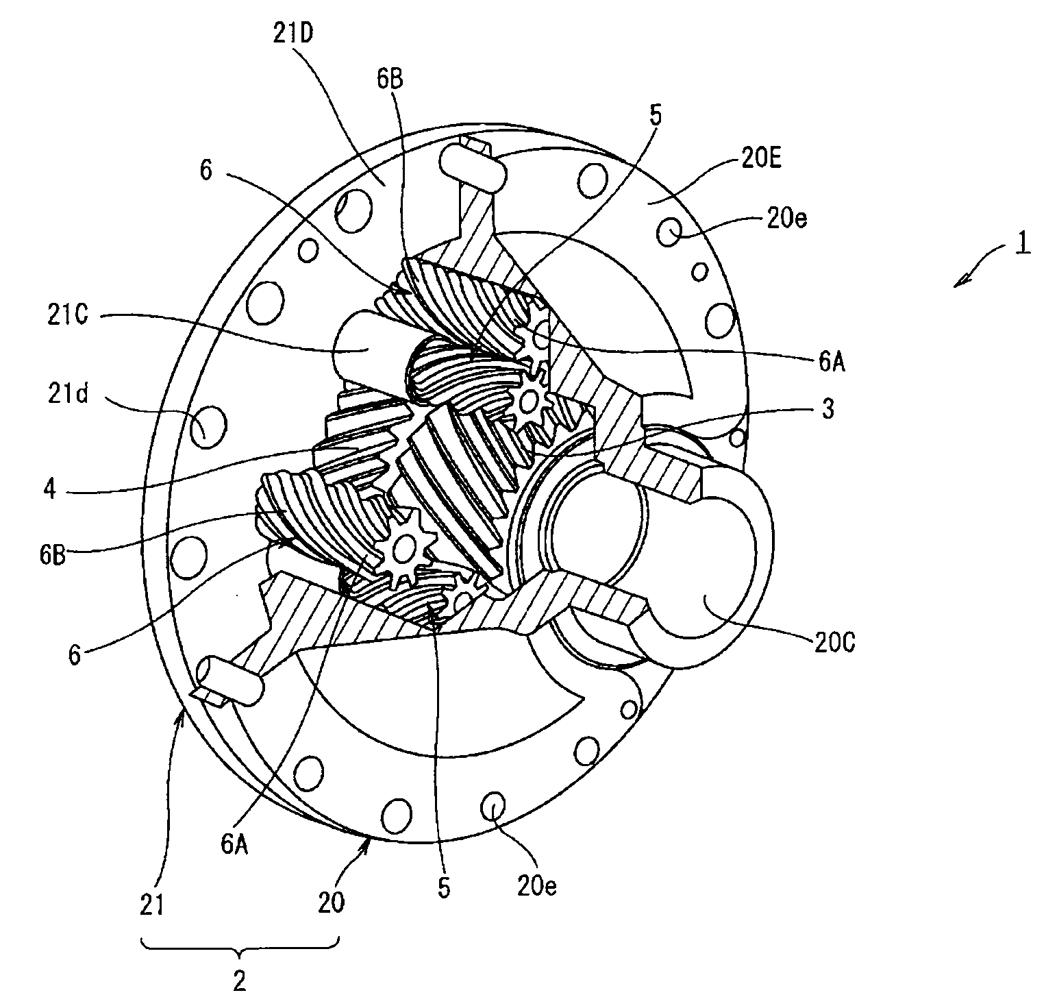
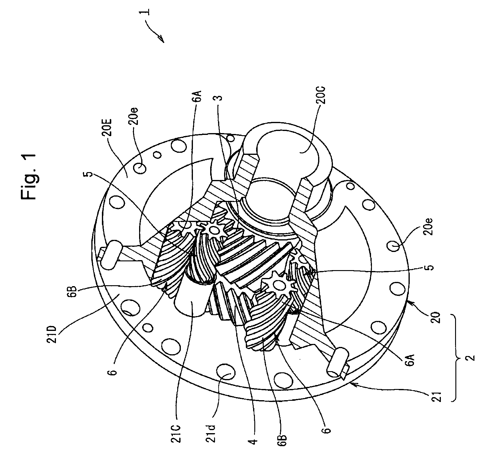
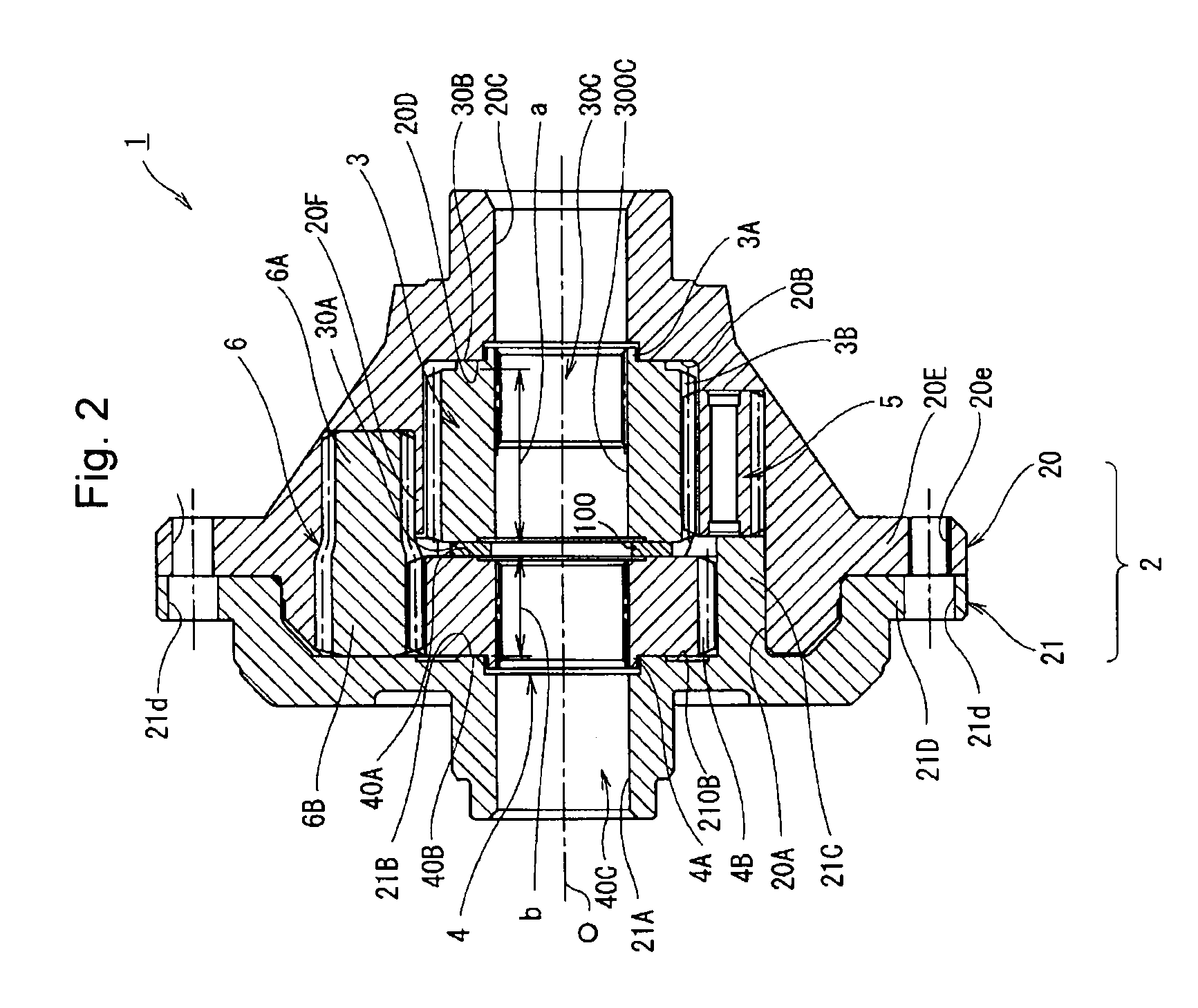
[0019]Second feature of the present invention provides a differential apparatus for a vehicle with a gear including mainly a pair of output gears, a first pinion gear intermeshing with one of output pinion gears with a parallel gear axis to the first pinion gear, a second pinion gear intermeshing with both of the other of output pinion gears and the first pinion gear with parallel gear axes to the second pinion gear respectively, and a differential case accommodating the pair of output gears, the first pinion gear and the second pinion gear, the second pinion gear has a large and a small gear portions each of which pitch diameter is different respectively and each of which tooth number is same respectively and a tooth lead and a tooth space formed to be shared by the large and the small gear portions continuously from the large gear portion to the small gear portion. Thereby, the differential apparatus for the vehicle with the gear according to the present invention can reduce the diameter of the second pinion and the set number of the pinion gear as the conventional apparatus needs so that it is restrained for the apparatus as a whole from being large, heavy and high cost.
[0023]Sixth feature of the present invention provides a differential apparatus for a vehicle with a gear constructed mainly that one of the output gears has a wider tooth width intermeshing with the first pinion gear than a tooth width of the other of the side gears intermeshing with the second pinion gear. Thereby, the side gear can intermesh with the first pinion gear over full wide range along its axial direction so that the first pinion gear can be stably intermeshed with the side gear and the second pinion gear, thereby achieving enough mechanical strength.

Problems solved by technology

However, in the prior art of the conventional differential device for the vehicle disclosed in the patent document, because there is the step portion, the mechanical strength of the second pinion gear according to torsion torque generated at the step portion is weak.
As a result, the apparatus itself becomes large when the diameter of the gear is large or the total cost of the apparatus becomes high when the set number is large.
However, it is difficult to achieve the completely same differential rotational ratio or differential restricting performance so that there happen any difference torque transmitting performance to the right and left tire shafts at a straight driving or any unbalance in the differential rotational ratio or the differential restricting performance at a right or left turning.

Method used


Image

  • Gear and differential apparatus provided therewith for vehicle
  • Gear and differential apparatus provided therewith for vehicle
  • Gear and differential apparatus provided therewith for vehicle

Examples


Embodiment Construction

[Whole Construction of the Differential Apparatus for the Vehicle]

[0031]In FIG. 1 and FIG. 2, a numeral 1 shows the differential apparatus for the vehicle according to one embodiment of the present invention. The differential apparatus 1 mainly constitutes of a differential case 2, a pair of side gears 3, 4, a first pinion gear 5 and a second pinion gear 6. The differential case 2 is rotated by receiving a torque from an engine. The pair of side gears 3, 4 are respectively positioned on a rotational axis O of the differential case 2 as an output gear. The first pinion gear 5 intermeshes or engages in mesh with the side gear 3 of the pair of side gears 3, 4 and the second pinion gear 6 intermeshes with both of the first pinion gear 5 and the side gear 4 respectively.

[Construction of the Differential Case 2]

[0032]As shown in FIGS. 1 and 2, the differential case 2 has a first case element 20 and a second case element 21 and is constructed as a hollow cylindrical body rotated around the...


PUM


Abstract

It is an object of the present invention to provide a differential apparatus for a vehicle with a gear obtaining a sufficient mechanical strength against any torsion torque and preventing from being large and heavy as a whole and preventing from making a high manufacturing cost.The differential apparatus for the vehicle with the gear comprises a pair of output gears 3, 4, a first pinion gear 5 intermeshing with one of output pinion gears 3, 4 with a parallel gear axis to the first pinion gear 5, a second pinion gear 6 intermeshing with both of the other of output pinion gears 3, 4 and the first pinion gear 5 with parallel gear axes to the second pinion gear 6 respectively, and a differential case 2 accommodating the pair of output gears 3, 4, the first pinion gear 5 and the second pinion gear 6. The second pinion gear 6 has a large and a small gear portions 6A, 6B each of which pitch diameter is different respectively and each of which tooth number is same respectively, and a tooth lead 60 and a tooth space 61 formed to be shared by the large and the small gear portions 6A, 6B continuously from the large gear portion 6B to the small gear portion 6A.

Description

INCORPORATION BY REFERENCE[0001]The present application claims priority under 35 U.S.C. §119 to Japanese Patent Application No. 2008-043019, filed on Feb. 25, 2008. The contents of the application are incorporated herein by reference in their entirety.BACKGROUND OF THE INVENTION[0002]1. Field of the Invention[0003]The present invention relates to a gear and a differential apparatus provided therewith for a vehicle, and more particularly relates to the gear having two gear portions and the differential apparatus with the gear for a vehicle disposed between a right and a left tire wheels or between front tire wheels and rear tire wheels.[0004]2. Description of the Related Art[0005]It is well known for this kind of the differential apparatus for the vehicle as shown in a prior art as disclosed in a document of a Tokkaihei No. 8-247253, especially in its FIG. 2, disclosing a plurality of pinion gears and the side gears, each axis of which is parallel each other.[0006]This conventional d...

Claims


Application Information

Patent Timeline
IPC IPC(8): F16H48/10F16H48/11F16H55/17
CPCF16H48/285Y10T74/19698Y10T74/19679
Inventor NISHIJI, MAKOTO
Owner JTEKT CORP
Learn More