Method for Centering Reciprocating Bodies and Structures Manufactured Therewith

Inactive Publication Date: 2009-09-03
SUPERCONDUCTOR TECHNOLOGIES INC
View PDF18 Cites 12 Cited by
  • Summary
  • Abstract
  • Description
  • Claims
  • Application Information

AI Technical Summary

Benefits of technology

[0023]It is yet a further object to simplify critical alignment processes in production.
[0024]It is yet a further object to increase p

Problems solved by technology

Second, gas is flowed through the inlet to the gas bearing (1) while the body is not coupled to a substantially laterally fixed structure (2) at a press

Method used


Image

  • Method for Centering Reciprocating Bodies and Structures Manufactured Therewith
  • Method for Centering Reciprocating Bodies and Structures Manufactured Therewith
  • Method for Centering Reciprocating Bodies and Structures Manufactured Therewith

Examples


Embodiment Construction

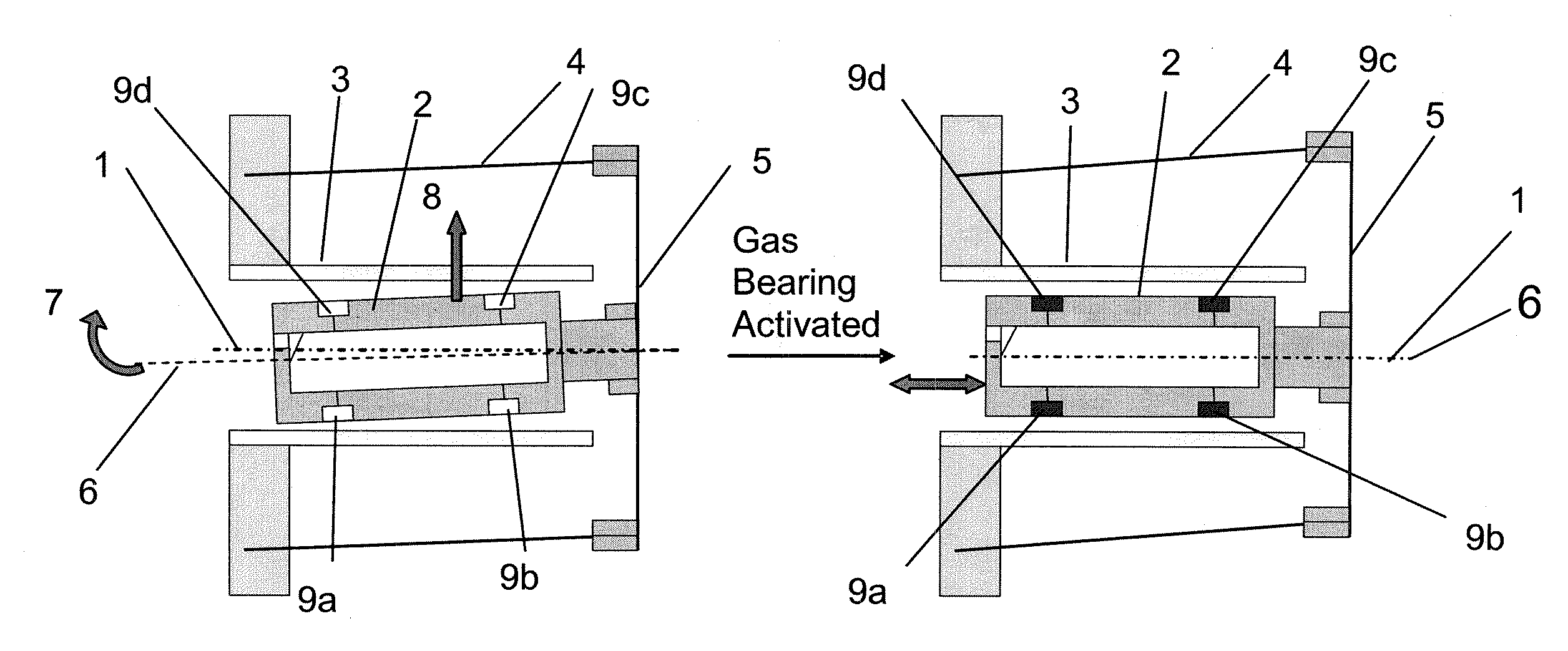
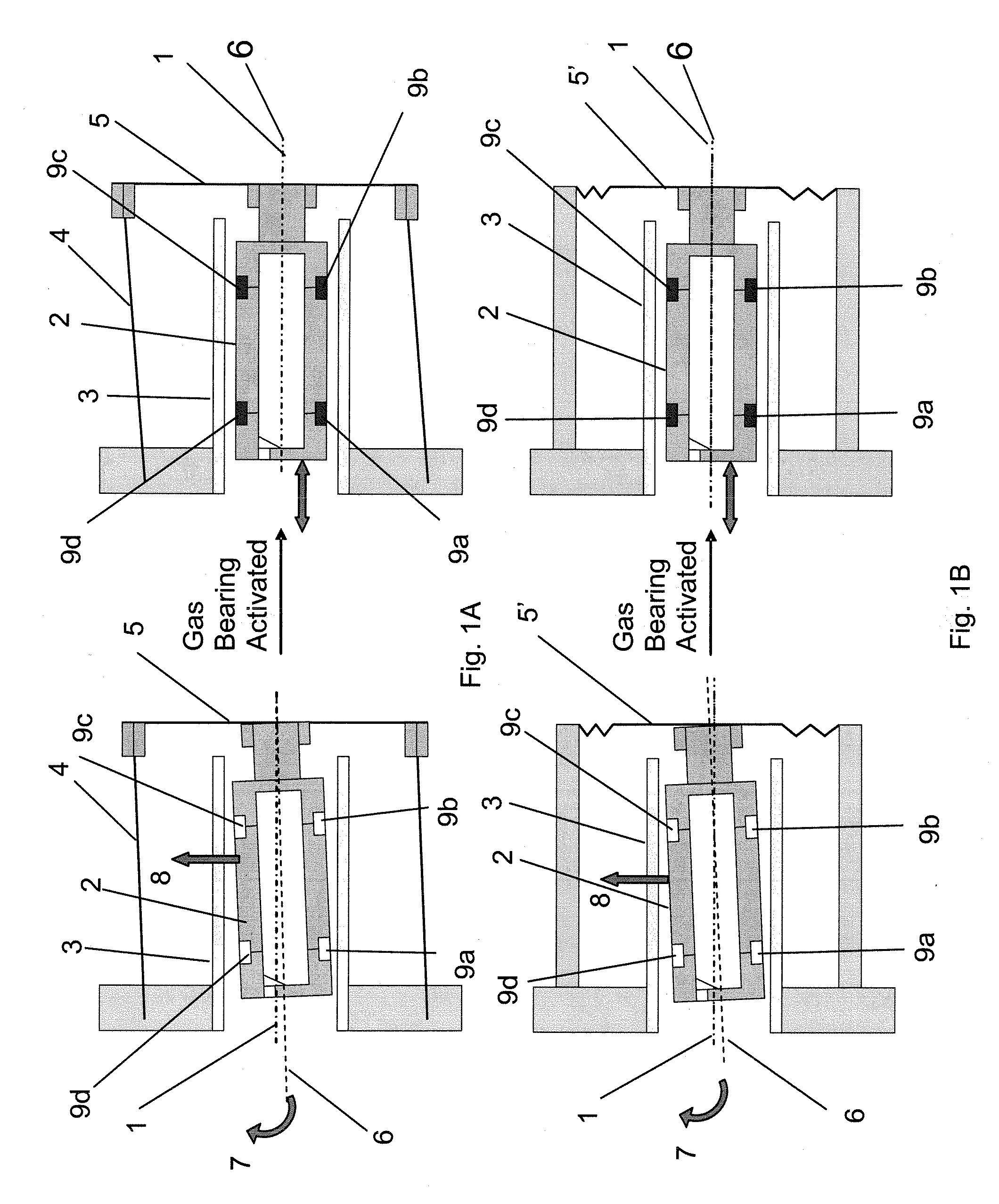
[0052]Turning to the drawings in more detail, FIGS. 1A-B illustrate a method for centering reciprocating bodies, such as a compressor piston for a linear Stirling cooler, equipped with a fluid bearing linked to a compliant structure. In FIG. 1A, piston 2 is configured to reciprocate in compressor bore 3 along the compressor bore symmetry axis 1. The piston 2 is connected to a leaf spring 5 and laterally compliant alternator rods 4 such that when gas bearings 9a-d are activated, the piston 2 and its symmetry axis 6 may rotate along the axis of symmetry 1, as shown by arrow 7, and also may move laterally in the direction of arrow 8 in order to become aligned within the compressor bore 3. Alternatively, as shown in FIG. 1B, a modified leaf spring 5′ can also be connected to the piston 2 and function as a laterally compliant component to allow for both rotation 7 and lateral movement 8 of the piston 2 to align the piston 2 in the compressor bore 3 and realize a non-friction bearing.

[005...


PUM

PropertyMeasurementUnit
Forceaaaaaaaaaa
Pressureaaaaaaaaaa
Currentaaaaaaaaaa

Abstract

Methods for assembling a reciprocating body, such as a piston, within a bore using a design are described. The piston is substantially centered within the bore and then connected at one end through a rotational coupling to a substantially laterally fixed structure connected to the bore such that during normal operation the piston can rotate within the bore along the bore axis of symmetry but can no longer move laterally. Before fixing the rotational coupling, the piston is connected to an external gas source and substantially aligned along the bore axis of symmetry by a gas bearing having one or more gas bearing ports disposed toward the bore. During normal operation, the gas bearing provides a rotational force sufficient to realize a non-frictional bearing between the piston and the bore. The method of assembly is particularly useful in the assembly of Stirling cycle cryocooler comprising a piston, a compressor bore, adapted to contain the piston, a gas inlet to the piston, a plurality of gas bearing ports located within the piston and disposed toward the compressor bore, the gas inlet being in fluid communication with the gas bearing ports, a rotational coupling structure attached to one end of the piston, and a substantially laterally fixed structure affixed to the compressor bore and the rotational coupling structure.

Description

RELATED APPLICATIONS[0001]This application claims the benefit of provisional application 60 / 659,434, filed Aug. 17, 2007, entitled “Method for Centering Reciprocating Bodies and Structures Manufactured Therewith,” which is hereby expressly incorporated by reference in its entirety.FIELD OF THE INVENTION[0002]These inventions relate to methods for centering reciprocating bodies within a bore, and structures manufactured using those techniques. More particularly, the methods and devices are particularly applicable for the assembly and design of cryocoolers and motors, most particularly Stirling cycle cryocoolers and motors.BACKGROUND OF THE INVENTION[0003]Various entities build Stirling coolers equipped with a fluid bearing linked to compliant structures, such as alternator rods. This design is used for centering the reciprocating compressor piston inside the compressor bore during normal operation.[0004]U.S. Pat. No. 5,525,845 describes a “compliant” linkage for mechanical transducer...

Claims


Application Information

Patent Timeline
IPC IPC(8): F02G1/053B23P17/00B23P11/00F25B9/14F01B29/10
CPCF25B9/14F25B2309/001Y10T29/4935Y10T29/49236Y10T29/49229Y10T29/4927
Inventor FIEDLER, ANDREAS
Owner SUPERCONDUCTOR TECHNOLOGIES INC
Why Eureka
Try Eureka