Scraper Blade and Method of Manufacturing the Same

Inactive Publication Date: 2009-09-03
METABO MINERALS SWEDEN
View PDF15 Cites 10 Cited by
  • Summary
  • Abstract
  • Description
  • Claims
  • Application Information

AI Technical Summary

Benefits of technology

[0023]at an optional point of time after arranging the polycarbonate plastic, supplying polyurethane to said cas

Problems solved by technology

For some applications, this type of homogeneous scraper has, however, been found to have insufficient abrasion resistance.
Furthermore the stiffening sheet-metal piece causes troubles when destructing the scraper since the materials have to be separated.
Therefore also this scraper is not quite optimal for said applications.
However, this solution causes unnecessary wear on the surface which is being scraped by means of the scraper.
The solution may also cause sparking and contamination of the material conveyed on the conveyor belt.
If the scraper is used as a prescraper for scraping a curved surface and therefore the scraper blade is oriented obliquely to this surface, there is a great risk that the laye

Method used


Image

  • Scraper Blade and Method of Manufacturing the Same
  • Scraper Blade and Method of Manufacturing the Same
  • Scraper Blade and Method of Manufacturing the Same

Examples


Example

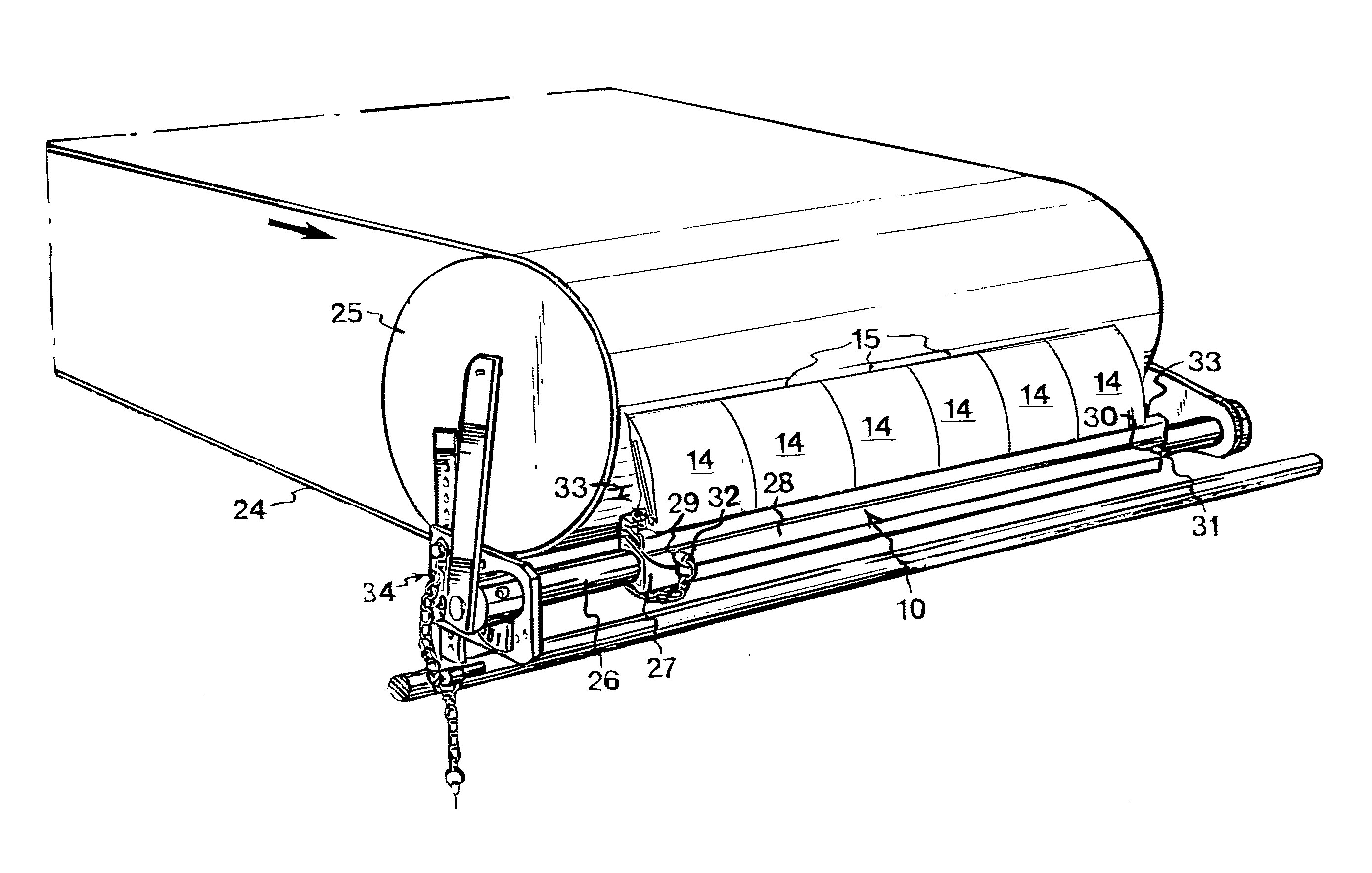
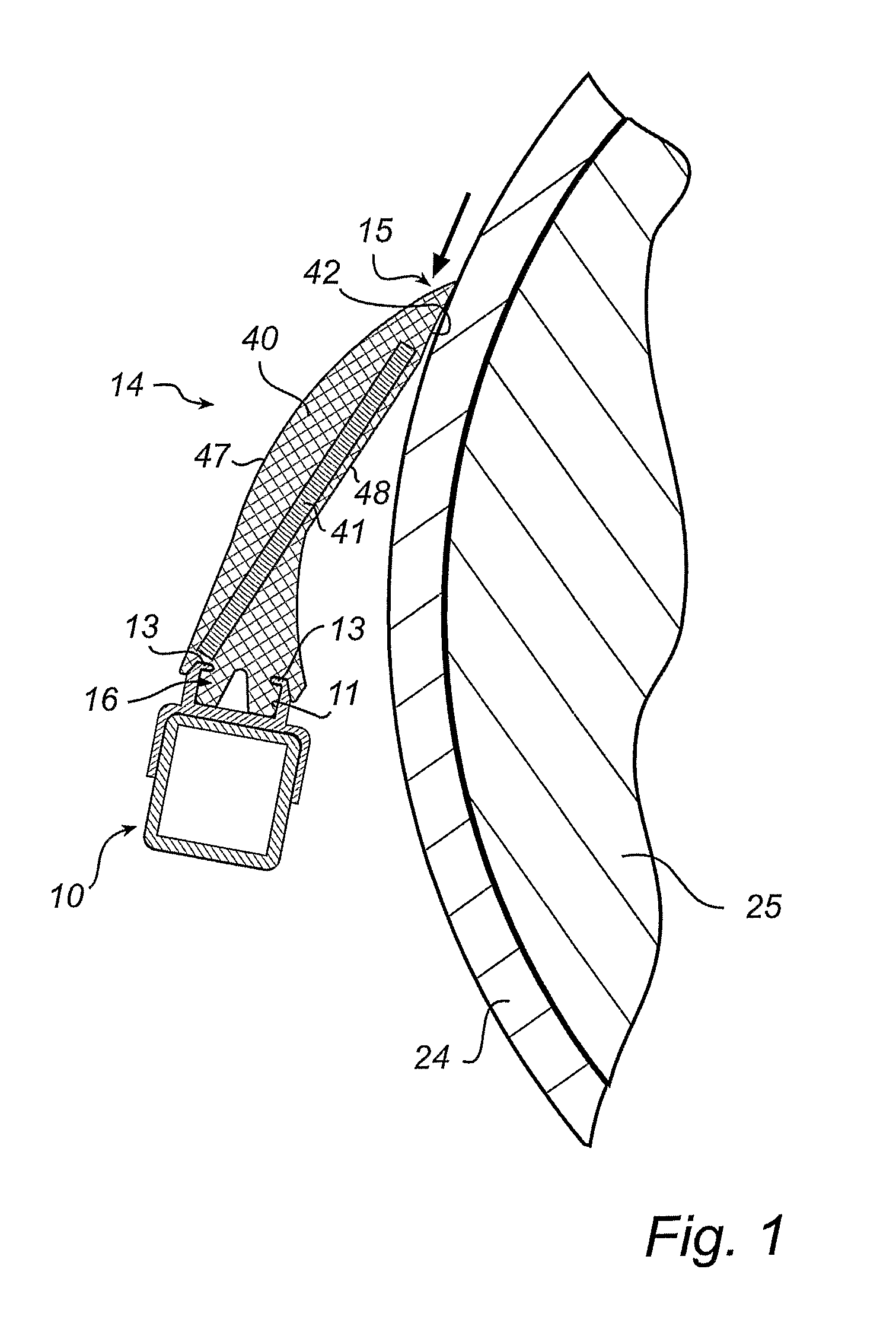
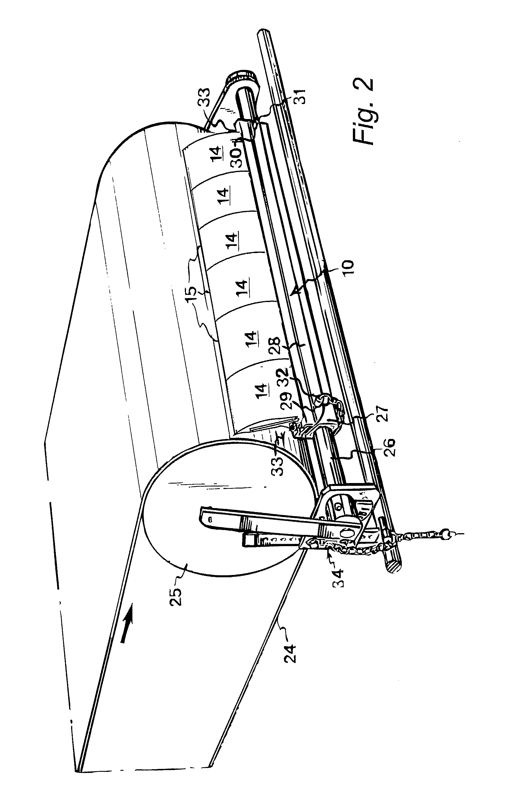
[0039]A scraper blade according to a variant of a first embodiment is shown in FIG. 3. Apart from the construction of the scraper blade in respect of material and layer structure, it is built in prior art manner. The mounting base 16 with its gripping groove 17 is formed in prior art manner in a base portion of the scraper, according to the above-mentioned prior art technique of the same Applicant, to be held by the supporting beam 10 designed in prior art manner, with its undercut mounting groove 11 which has inwardly directed flanges 13.

[0040]The function of this fastening device and the associated control is described in the above-mentioned patent application and will thus not be described in more detail.

[0041]In the first embodiment, the scraper blade 14 has an outer cover 40 of a soft hardwearing PU material with a plate 41 of PC, fixed by casting, extending substantially throughout the transverse direction of the scraper relative to the conveyor belt in a position of use. As w...

Example

[0048]FIG. 4 shows a second embodiment of the invention. Here a core 40 of the scraper blade and the mounting base consist of a continuous PU material, while the PU reinforcement / stiffening 41 is arranged on the upper side and underside of the scraper blade and extends from the tip of the scraper down to the mounting base. This sandwich construction combined with the good properties of the materials makes it possible to manufacture a scraper blade 14 with good scraping properties while using relatively small amounts of materials.

Example

[0049]FIG. 5 shows a third embodiment of the present invention. In this embodiment, the mounting base 16 and the long side which in use faces the conveyor belt are made of the same PC component 41. A main scraper layer 40 of PU is arranged on the opposite long side of the scraper blade 14. In the construction, the PC component 41 is self-supporting, and therefore a still softer and more abrasion resistant PU material can be used for the scraper layer 40. Also layers that are softer than the above-mentioned 50° Shore A are anticipated.


PUM

PropertyMeasurementUnit
Timeaaaaaaaaaa
Angleaaaaaaaaaa
Angleaaaaaaaaaa

Abstract

A scraper blade adapted to scrape off material from a surface has a scraper tip at one end and a mounting base at its other end and is tapered towards the tip at least in the outer end of the scraper blade, its scraper blade portion which extends from the tip and to a point adjacent to or in the mounting base being made with at least two layers, which extend longitudinally along said scraper blade portion, and is characterised in that at least one first layer is made of polyurethane with a lower hardness and a higher abrasion resistance than at least one second layer which is mainly made of polycarbonate plastic, said at least one second polycarbonate plastic layer being adapted to reinforce and stiffen said at least one first layer, which constitutes a main contact surface against said surface.

Description

FIELD OF THE INVENTION [0001]The present invention relates to a scraper blade for use in particular as a conveyor belt scraper.BACKGROUND ART [0002]SE-B-468 390 and its equivalent U.S. Pat. No. 5,197,587 disclose a scraper blade which is adapted to be used in a conveyor belt scraping device. This scraper is made of a homogeneous elastomeric or plastic material and is provided with an inner stiffening in the form of a sheet-metal piece which is inserted into a groove in the scraper. For some applications, this type of homogeneous scraper has, however, been found to have insufficient abrasion resistance. Furthermore the stiffening sheet-metal piece causes troubles when destructing the scraper since the materials have to be separated.[0003]A similar scraper is disclosed in EP-A-0 893 376. This scraper has an inner stiffening corresponding to the detachable stiffening in the scraper according to the above-mentioned document. Otherwise it is similar, that is the active scraper tip is mad...

Claims


Application Information

Patent Timeline
IPC IPC(8): B65G45/12B65G45/16B29C39/10
CPCB29C70/68B65G45/16B65G45/12
Inventor GRONVALL, LARSABRAHAM, ROBERT
Owner METABO MINERALS SWEDEN
Why Eureka
Try Eureka