
Aircraft structure with hinge rib assembly

a technology of hinge ribs and aircraft, which is applied in the direction of fuselages, manufacturing tools, transportation and packaging, etc., can solve the problems of snagging or damage, system complexity, and awkward installation of/b>

Inactive Publication Date: 2009-09-03
AIRBUS OPERATIONS LTD
View PDF3 Cites 24 Cited by
  • Summary
  • Abstract
  • Description
  • Claims
  • Application Information

AI Technical Summary

Benefits of technology

[0012]Providing the hinge rib as an assembly of two parts provides a number of advantages, including (but not limited to):
[0014]the ability to install or remove the hinge rib without having to move it inboard along the structure;
[0016]the ability to install one or more elongate lines which extend in a span-wise direction along the aircraft structure more easily (typically before step b) and / or before step c)).

Problems solved by technology

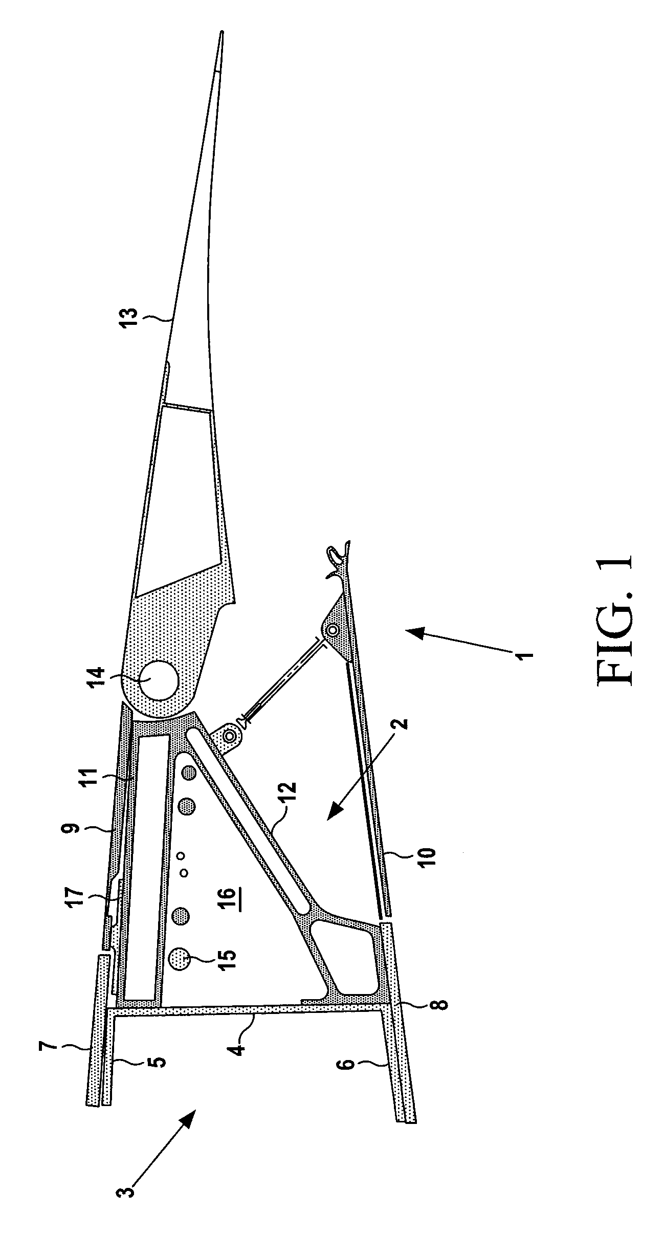
These lines 15 can be awkward to install, as they need to be pulled through the gap 16 progressively, incurring a risk of snagging or damage.
This continuing reduction in size, coupled with an increase in systems complexity, makes existing hinge rib designs increasingly difficult to implement.
A further problem with the conventional hinge rib design is as follows.
As a result it is not possible install or remove the hinge rib 2 by moving it fore or aft respectively.
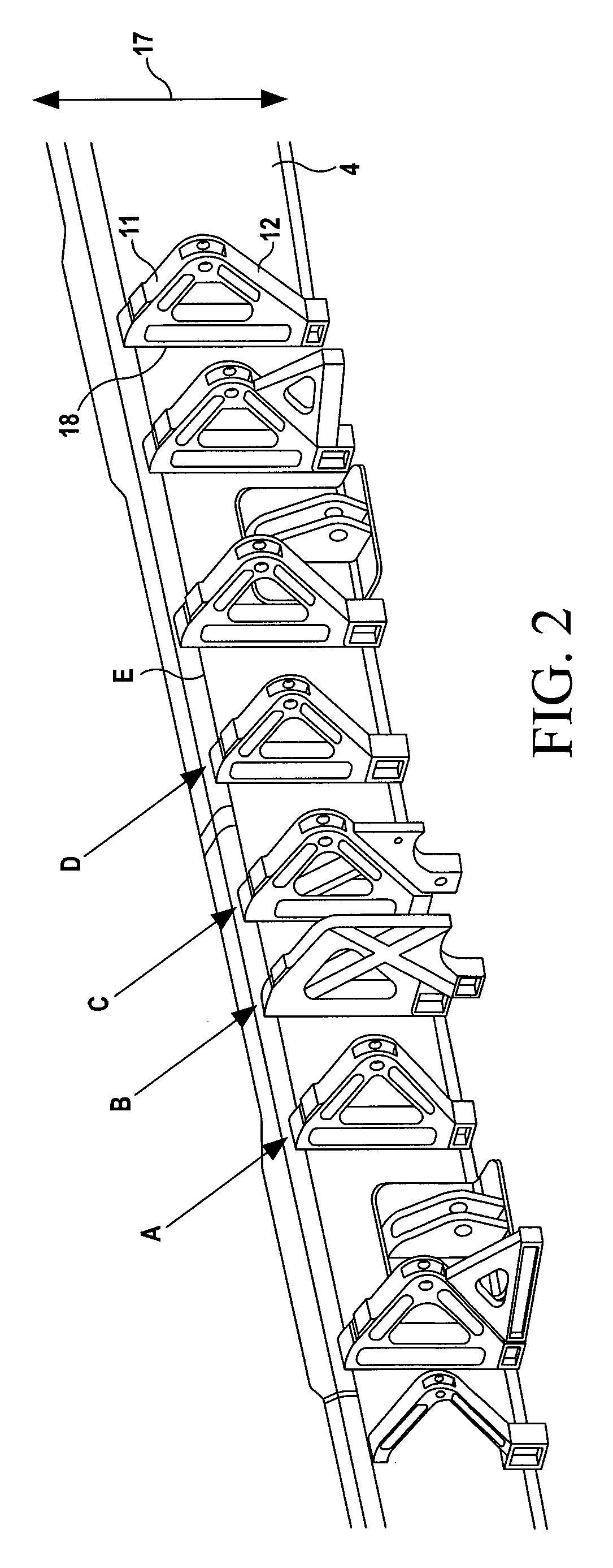
This can create complications during maintenance or installation of the hinge ribs 2. FIG. 2 shows a line of hinge ribs, each attached to the web 4 of a C-section rear spar.
This requires the otherwise unnecessary removal of neighbouring hinge ribs B, C and D, adding complexity and cost to the maintenance operation.
Using the traditional single piece A-frame design for the hinge rib also does not make optimum use of the material or billet from which the hinge rib is machined, resulting in a large amount of waste.
Also the grain flow in the billet can never be fully structurally optimized as the longitudinal grain flow of the material can never be aligned to both the legs of the A-frame, which may be at angles of up to 90 degrees to each other.
Alternative hinge rib designs such as shear webs can offer a more weight optimized structural solution but may be less efficient in material cost and are worse for systems installation.
Also shear webs can cause significant thermal problems as they will tend to act as baffles to any global airflow that would normally aid the cooling process along the trailing edge of the wing.

Method used


Image

  • Aircraft structure with hinge rib assembly
  • Aircraft structure with hinge rib assembly
  • Aircraft structure with hinge rib assembly

Examples


Embodiment Construction

)

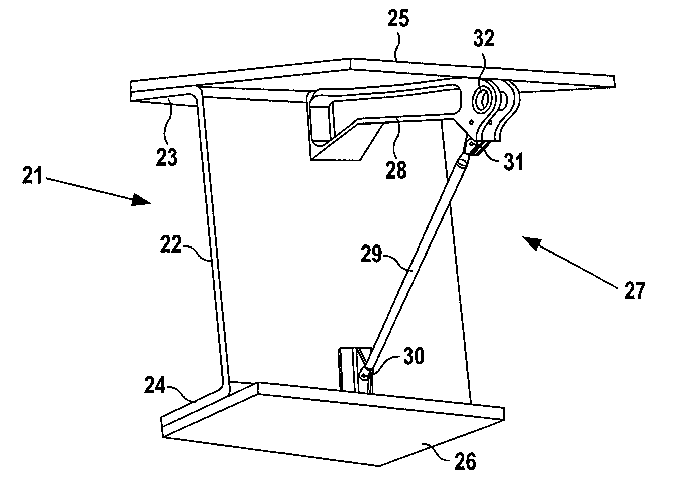
[0043]FIGS. 3 and 4 show part of the trailing edge of a wing comprising a C-section rear spar 21 with a web 22 and upper and lower flanges 23, 24. Composite upper and lower covers 25, 26 are attached to the upper and lower flanges. A variety of types of composite material may be used, but most typically the covers are formed from a laminar composite material, each ply comprising a set of unidirectional carbon fibres impregnated with an epoxy resin matrix. The covers each extend forward of the spar flanges to form the upper and lower boundaries of a wing box (not shown). They also extend aft of the spar web to form respective overhanging portions shown in FIGS. 3 and 4. A two-part hinge rib assembly 27 connects a spoiler 70 (shown in FIG. 7) to the overhanging portions of the upper and lower covers 25, 26 and to the spar web 22.

[0044]The hinge rib assembly 27 comprises an upper hinge rib arm 28 and a lower hinge rib arm 29 which extends longitudinally at an acute angle to the upper ...


PUM

PropertyMeasurementUnit
anglesaaaaaaaaaa
structureaaaaaaaaaa
cross-sectional areaaaaaaaaaaa

Abstract

An aircraft structure comprising; a rear spar, an upper cover which is attached to the rear spar and overhangs to its rear; a lower cover which is attached to the rear spar and overhangs to its rear, a hinge rib assembly comprising: a first hinge rib arm attached to a first one of the covers; and a second hinge rib arm connected to the first hinge rib arm and attached to a second one of the covers; and an aerodynamic control element pivotally mounted to the hinge rib assembly. The first and second hinge rib arms are separate parts. This provides the ability to disassemble the hinge rib in-situ for repair or maintenance purposes; the ability to install or remove the hinge rib without having to move it inboard along the structure; reduced material wastage during manufacture; and the ability to install one or more elongate lines which extend in a span-wise direction along the aircraft structure.

Description

FIELD OF THE INVENTION[0001]The invention relates to a hinge rib assembly for pivotally mounting an aerodynamic control element to an aircraft structure, an aircraft structure incorporating such a hinge rib assembly, and a method of installing an aerodynamic control element using such a hinge rib assembly.BACKGROUND OF THE INVENTION[0002]FIG. 1 shows a trailing edge 1 of a conventional aircraft wing comprising a C-section rear spar 3 consisting of a spar web 4 and upper and lower flanges 5, 6. Upper and lower covers 7, 8 are attached to the upper and lower flanges 5, 6 of the spar 3 and extend to its rear. An upper panel 9 is attached to the upper cover 7 with a butt-strap 17. A hinge rib 2 comprises two integrally formed arms 11, 12 forming a so-called “A-frame”. The upper arm 11 is attached to the upper cover 7 via the butt-strap 17 and its foot is attached to the spar web 4. The foot of the lower arm 12 is attached to the lower cover 8 and to the spar web 4. A spoiler 13 is pivot...

Claims


Application Information

Patent Timeline
Patent Type & Authority Applications(United States)
IPC IPC(8): B64C1/06B23P19/00
CPCB64C9/02Y10T29/49815Y02T50/44Y02T50/32Y02T50/30Y02T50/40
Inventor MCALINDEN, JONSHARP, KIM
Owner AIRBUS OPERATIONS LTD
Learn More