
Reception apparatus, reception method and program

a technology of reception apparatus and reception method, applied in the field of reception apparatus, a reception method and a program, can solve problems such as and achieve the effect of preventing deterioration of reception performan

Inactive Publication Date: 2009-09-03
SONY CORP
View PDF3 Cites 13 Cited by
  • Summary
  • Abstract
  • Description
  • Claims
  • Application Information

AI Technical Summary

Benefits of technology

[0054]Thus, it is desirable to provide a reception apparatus, a reception method and a program which can prevent deterioration of the reception performance.
[0060]According to a further embodiment of the present invention, there is provided a reception apparatus including FFT mathematical operation means for carrying out FFT mathematical operation for an OFDM time domain signal, pilot signal extraction means for extracting pilot signals from an OFDM frequency domain signal obtained by carrying out the FFT mathematical operation by the FFT mathematical operation means, estimation means for estimating a characteristic of a transmission line corresponding to each of the pilot signals and interpolating the characteristic of the transmission line in a time direction to determine transmission line characteristics for every predetermined subcarriers, control means for controlling the width and the center position of the passband of an interpolation filter to be used for a frequency interpolation process of filtering the transmission line characteristics for every predetermined subcarriers to interpolate the transmission line characteristics in a frequency direction, interpolation means for carrying out a process of carrying out the frequency interpolation process using the interpolation filter to determine transmission line characteristics of all subcarriers while varying the width and the center position of the passband of the interpolation filter under the control of the control means with regard to the transmission line characteristics for every predetermined subcarriers determined from the OFDM frequency domain signals representative of the same symbol, distortion correction means for correcting distortion of the OFDM frequency domain signals representative of the same symbol using the transmission line characteristics of all subcarriers determined by the interpolation means, calculation means for calculating the quality of the OFDM frequency domain signals whose distortion is corrected, selection means for selecting, based on the qualities calculated by the calculation means, an interpolation filter which is used to obtain that one of the OFDM frequency domain signals after the distortion correction which exhibits the best quality, variable coefficient interpolation means for carrying out the frequency interpolation process for the transmission line characteristics for every predetermined subcarriers determined by the estimation means using an interpolation filter having the same characteristic as that of the interpolation filter selected by the selection means with regard to the width and the center position of the passband to determine the transmission line characteristics of all subcarriers, and equalization means for correcting distortion of the OFDM frequency domain signals using the transmission line characteristics of all subcarriers determined by the variable coefficient interpolation means to carry out equalization.
[0070]With the reception apparatus, reception methods and programs, deterioration of the reception performance can be prevented.

Problems solved by technology

Since distortion of the transmission line may not be compensated for sufficiently, this makes a cause of deterioration of the reception performance.

Method used


Image

  • Reception apparatus, reception method and program
  • Reception apparatus, reception method and program
  • Reception apparatus, reception method and program

Examples


first embodiment

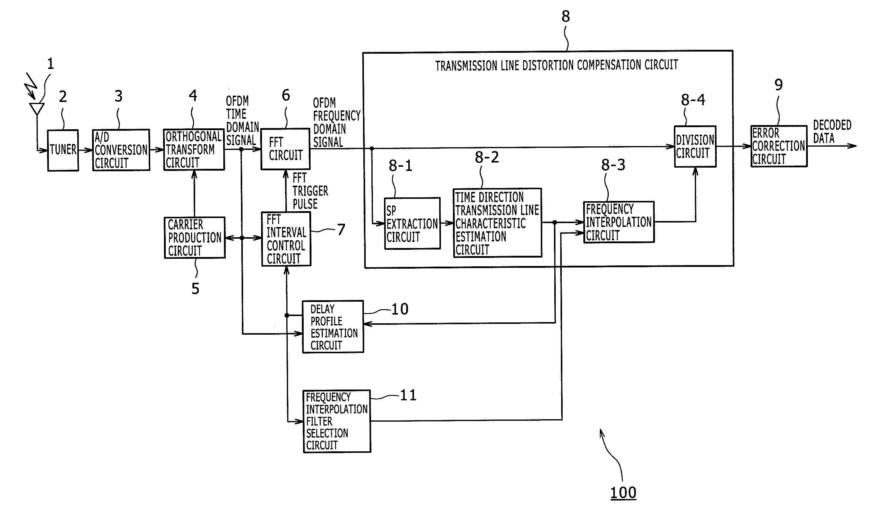
[0102]FIG. 7 shows an example of a configuration of an OFDM receiver according to an embodiment of the present invention.

[0103]Referring to FIG. 7, the OFDM receiver 101 shown includes a reception antenna 1, a tuner 2, an A / D conversion circuit 3, an orthogonal demodulation circuit 4, a carrier production circuit 5, an FFT circuit 6, an FFT interval control circuit 7, a transmission line distortion compensation circuit 8, an error correction circuit 9, a delay profile estimation circuit 10, a frequency interpolation filter selection circuit 11 and an optimum frequency interpolation filter selection circuit 21. The OFDM receiver 101 is different from the OFDM receiver 100 shown in FIG. 3 in that it additionally includes the optimum frequency interpolation filter selection circuit 21.

[0104]The tuner 2 frequency converts an RF signal received by the reception antenna 1 into an IF signal and outputs the IF signal to the A / D conversion circuit 3.

[0105]The A / D conversion circuit 3 carries...

second embodiment

[0199]While the foregoing description relates to a case wherein the width of the passband or filter band of an interpolation filter is adjusted to improve the signal quality, the center position or center frequency of the passband may be adjusted in addition to the width of the passband.

[0200]FIGS. 16A to 16D illustrate the signal quality where the width of the passband of an interpolation filter is variable while the center position of the passband is fixed.

[0201]In FIGS. 16A to 16D, the horizontal direction indicates the time direction and the vertical direction indicates the power of the path. An upwardly directed void triangle represents the position of the center of the passband of an interpolation filter.

[0202]FIG. 16A illustrates an example of a profile of a reception signal. The reception signal is received through paths P, Q and R.

[0203]If such an interpolation filter which may not include some of the paths in the passband thereof is applied as seen in FIG. 16B or 16C, then...


PUM


Abstract

A reception apparatus including an extraction section; a transmission line characteristic estimation section; an interpolation section; a compensation section; a detection section; and a selection section.

Description

BACKGROUND OF THE INVENTION[0001]1. Field of the Invention[0002]This invention relates to a reception apparatus, a reception method and a program.[0003]2. Description of the Related Art[0004]As one of modulation methods for a ground wave digital broadcast, an orthogonal frequency division multiplexing (OFDM) method has been proposed wherein a large number of orthogonal carriers are used and modulated by phase shift keying (PSK) or quadrature amplitude modulation (QAM).[0005]The OFDM method has a characteristic that, since an entire transmission band is divided by a large number of subcarriers, the bandwidth per one subcarrier is narrow and, although the transmission speed per one subcarrier is low, the total transmission speed is equal to that of existing modulation methods.[0006]The OFDM has another characteristic that, since a large number of subcarriers are transmitted in parallel, the symbol rate is low. Therefore, the time length of multipaths relative to the time length of one...

Claims


Application Information

Patent Timeline
Patent Type & Authority Applications(United States)
IPC IPC(8): H04B1/10
CPCH04B1/1036H04L25/0232H04L25/0216H04L5/0048
Inventor KAWAUCHI, HIDETOSHIYUBA, TADAAKIMIYAUCHI, TOSHIYUKIYOKOKAWA, TAKASHIOKAMOTO, TAKUYAIKEDA, TAMOTSUNANIWADA, KOJISHIMIZU, KAZUHIROMICHAEL, LACHLAN BRUCE
Owner SONY CORP
Learn More