Temperature control system

a temperature control and control system technology, applied in the field of temperature control systems, can solve the problems of increasing carbon dioxide, deteriorating performance of running, and affecting the performance of electric vehicles and the like, so as to prevent the deterioration of automobile and the like performance, control easily and efficiently, and maintain the effect of low consumption of power for secondary cells or the lik

Inactive Publication Date: 2013-11-14
MIHAMA
View PDF4 Cites 1 Cited by
  • Summary
  • Abstract
  • Description
  • Claims
  • Application Information

AI Technical Summary

Benefits of technology

[0045]With the temperature control system of the present invention, in an electric vehicle and the like, the temperature of a portion of an automobile and the like can be controlled easily and efficiently even in a cold region or the like, whereby deterioration of the performances of the automobile and the like can be prevented so that the automobile can run in the comfortable environment. Moreover, consumption of power of the secondary cell or the like can be kept low exceedingly in heating a portion of the automobile, and a travel distance of an automobile can be prolonged, and the life of the battery can be extended.
[0046]In addition, the catalytic heater can be made compact, and moreover, the design of an automobile can be influenced, and a work in maintenance can be facilitated.

Problems solved by technology

Recently, an increase in carbon dioxide has been cited as one of environmental problems.
These electric vehicles and the like are effective as a measure against the environmental problems as above, but problems have been cited relating to performances of the automobile itself on the other hand.
If an air temperature falls low in a cold region or the like, for example, the electric vehicles and the like cannot be started relatively smoothly.
Moreover, performances of running also deteriorate.
Furthermore, seats and the like get cold in the cold region.
Thus, in the case of a secondary cell, charging frequency becomes high, and the life of a battery itself becomes short.

Method used


Image

  • Temperature control system
  • Temperature control system
  • Temperature control system

Examples


example 1

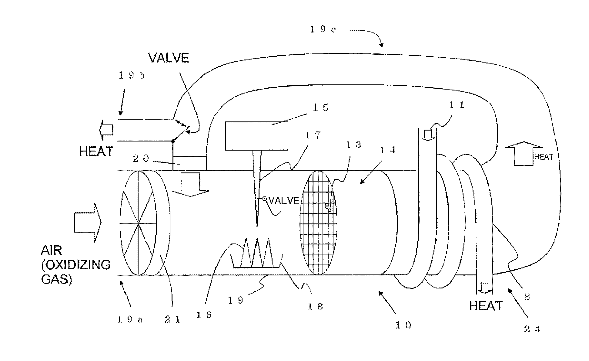
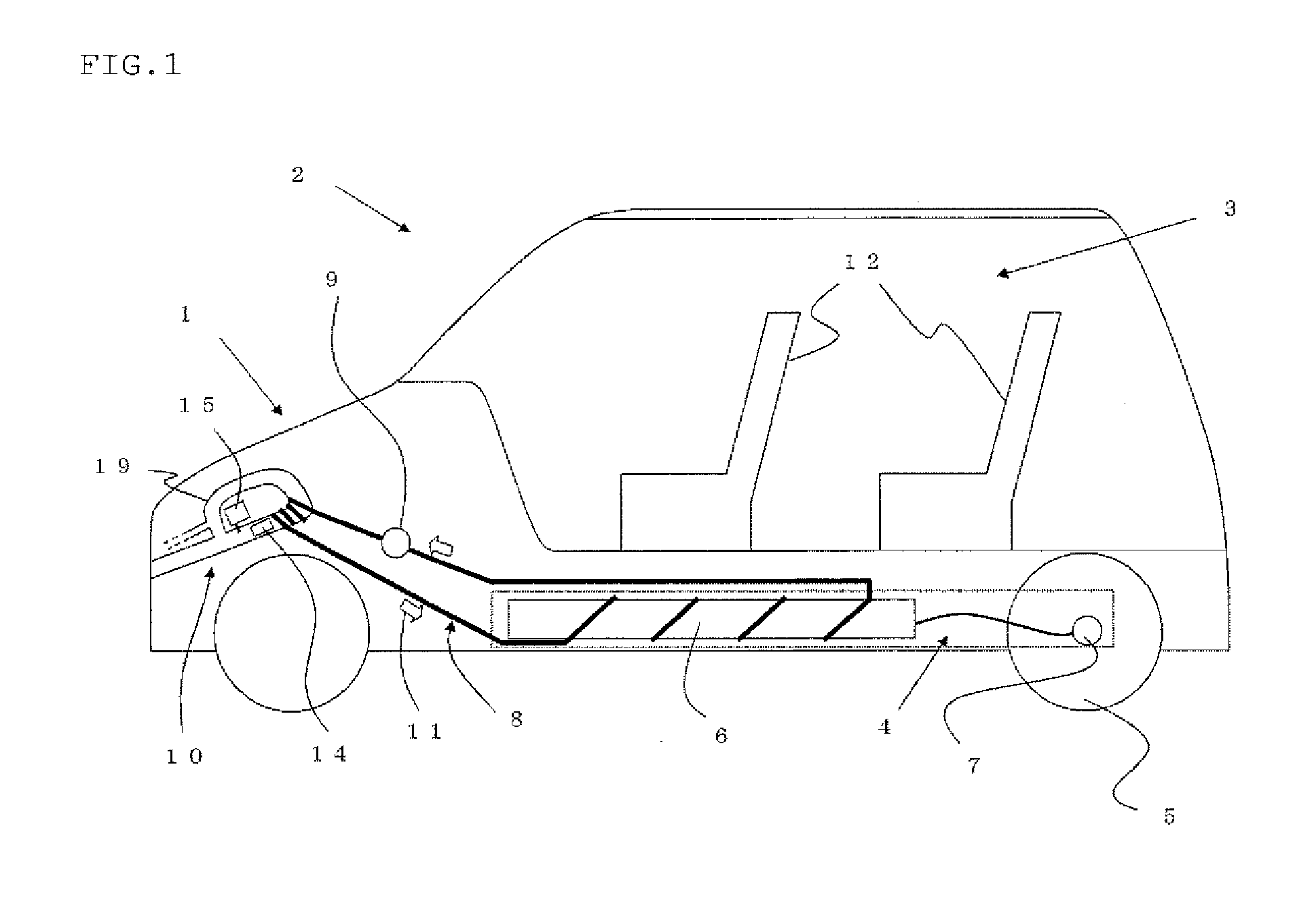
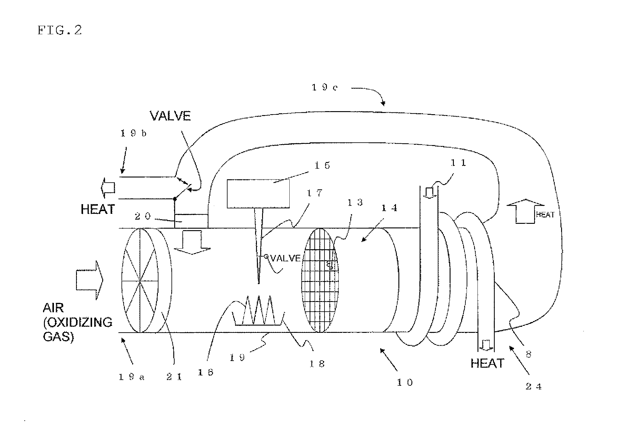
[0153]The temperature control system 1 of the present invention having the catalytic heater 10 as illustrated in FIG. 2 was prepared (the liquid sending pipe 8 was inserted into the seat 12 prepared separately as in FIG. 8), and by using such temperature control system of the present invention, an experiment was conducted in which, under an environment with an outside air temperature of 0° C., air and a fuel were made to react with each other on the catalyst 13 in the catalytic heater 10 and a part of them was circulated so as to generate heat and to heat the secondary cell 6 and the seat 12 through the liquid sending pipe 8 and the temperature-control duct 27, and a space having substantially the same size as that of the cabin was heated through the air-conditioning duct 28 for a predetermined period of time and kept at a certain temperature (20° C.) (a system as in FIG. 10).

[0154]The secondary cell and the seat were heated so as to have the same temperature when the outside air te...

example 2

[0162]In addition to the equipment similar to that in the Example 1, the thermoelectric element 26 was further arranged.

[0163]The thermoelectric element 26 was connected to the vicinity of the catalyzer 14 and the downstream thereof in the duct 19 as illustrated in FIG. 9. Only a small amount of methanol which is the fuel was supplied, and power generation was attempted by the Seebeck effect caused by a temperature difference at the aforementioned spot while the system was operating.

[0164]When the temperature of the vicinity of the catalyzer at this time (defined as a temperature of the catalyzer) and the temperature of the downstream region thereof (defined as a temperature of the gas after reaction) were measured, a graph in FIG. 13 was obtained.

[0165]As is known from FIG. 13, the temperature of the catalyzer itself rises to approximately 200° C. On the other hand, the gas temperature rises to approximately 430° C. By means of the temperature difference of as much as 200° C. or mo...


PUM


Abstract

An automobile temperature control system has a motor chamber on which a secondary cell or a fuel cell is mounted for driving wheels by a motor and a cabin and controlling a temperature of portions of the automobile. The temperature control system includes at least one catalytic heater and a fuel tank. The catalyst heater generates heat when an oxidizing gas and fuel from the fuel tank are supplied to the catalyst. At least part of the gas supplied to the catalyst and heated by the generated heat is subjected to circulative supply to the catalyst. The temperature of the portion of the automobile is controlled by using heat generated by the catalytic heater. As a result, a system is provided that efficiently controls the temperature of a portion of the automobile so that performance deterioration is prevented and comfortable running is realized even in a cold region.

Description

TECHNICAL FIELD[0001]The present invention relates to a system for controlling a temperature of a portion of an automobile in which wheels are driven by a motor by using a secondary cell or a fuel cell as in electric vehicles, hybrid (gasoline engine electricity) vehicles, fuel-cell vehicles and the like for example.BACKGROUND ART[0002]Recently, an increase in carbon dioxide has been cited as one of environmental problems. Carbon dioxide is cited as one of factors causing global warming, and an attempt has been made to suppress its generation, for example, a gas amount exhausted from an automobile and the like.[0003]Thus, expectation has been risen for development of electric vehicles, hybrid vehicles, fuel-cell vehicles and the like (hereinafter referred to as electric vehicles and the like) which do not emit carbon dioxide or in which generation of carbon dioxide can be suppressed better than prior-art vehicles (See Patent Literature 1).[0004]These electric vehicles and the like a...

Claims


Application Information

Patent Timeline
Patent Type & Authority Applications(United States)
IPC IPC(8): B60H1/22
CPCB60H1/2206B60H1/2209B60H1/2212H01M2220/20H01M2250/20H01M10/615H01M10/66Y02T90/40Y02E60/50Y02E60/10H01M8/00B60H1/22
Inventor MIHAMA, TAKESHIYAMABE, KENICHIRO
Owner MIHAMA
Why Eureka
Try Eureka