Biomass particle burner with vane drum type furnace bridge

A biomass particle and drum furnace technology, which is applied in the direction of combustion equipment, solid fuel combustion, lighting and heating equipment, etc. It can solve the abnormal combustion conditions in the furnace, the impact on production and life, and the grate is easy to slag and block, etc. problems, to achieve the effect of solving difficult slag removal, short slag removal time, improving combustion efficiency and utilization rate

Inactive Publication Date: 2016-08-03
黄辉
View PDF6 Cites 3 Cited by
  • Summary
  • Abstract
  • Description
  • Claims
  • Application Information

AI Technical Summary

Problems solved by technology

The use of grate intermittent slagging has a low degree of automation, and the grate is easy to slag and block, which will cause abnormal combustion in the furnace and affect normal production and life.
The slag pushing screw is used for continuous slagging, and when the coke-prone biomass particles are used, the screw is locked by coke slag. There are certain requirements for the selection of biomass particles, and the slagging screw continuously discharges slagging, and the slagging speed is too fast , there is a problem that biomass particles are discharged out of the furnace without being fully burned, resulting in waste of biomass resources

Method used


Image

  • Biomass particle burner with vane drum type furnace bridge
  • Biomass particle burner with vane drum type furnace bridge
  • Biomass particle burner with vane drum type furnace bridge

Examples


Embodiment 1

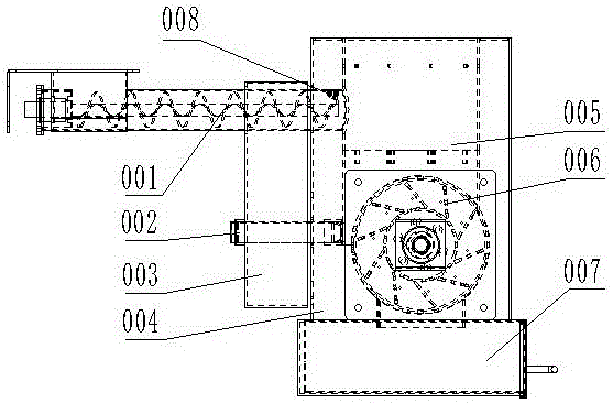
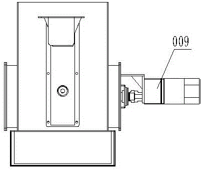
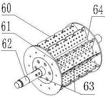
[0020] A blade drum type furnace bridge biomass particle burner, which consists of a combustion part and a slag discharge part. The combustion part consists of a combustion chamber (005), an auger feeder (001), an igniter (002), a setting The air channel chamber (004) outside the combustion chamber is composed of the air supply box (003) arranged on the side of the air duct chamber. The air channel chamber and the air supply box are set, and the slag discharge part is composed of the blade drum type furnace bridge (006), the slag receiving box (007) arranged under the blade drum type furnace bridge, and the transmission device that drives the blade drum type furnace bridge to rotate (009), the blade drum type furnace bridge is composed of a drum shaft (62), a drum (61) and a blade (60), the drum shaft and the drum are both hollow cylinders, and the drum shaft and the drum are Ventilation holes (63) are all provided, the blades are arranged on the drum, and the drum shaft is sl...

Embodiment 2

[0027] A blade drum type furnace bridge biomass particle burner, which is composed of a combustion part and a slag discharge part. The air supply box on one side of the air duct chamber is composed of the slag discharge part arranged under the combustion chamber, the auger feeder and igniter are arranged through the air duct chamber and the air supply box, and the slag discharge part is composed of The blade drum type furnace bridge is composed of a slag receiving box arranged under the blade drum type furnace bridge, and a transmission device that drives the rolling furnace bridge to rotate. The blade drum type furnace bridge is composed of a drum shaft, a drum and blades. The drum Both the shaft and the drum are hollow cylinders, and ventilation holes are arranged on the drum shaft and the drum, and the blades are arranged on the drum.

[0028] There are ten blades, and each blade is provided with a plurality of oxygen supply ventilation holes.

[0029] The edges of the bla...

Embodiment 3

[0034] A blade drum type furnace bridge biomass particle burner, which is composed of a combustion part and a slag discharge part. The air supply box on one side of the air duct chamber is composed of the slag discharge part arranged under the combustion chamber, the auger feeder and igniter are arranged through the air duct chamber and the air supply box, and the slag discharge part is composed of The blade drum type furnace bridge is composed of a slag receiving box arranged under the blade drum type furnace bridge, and a transmission device that drives the rolling furnace bridge to rotate. The blade drum type furnace bridge is composed of a drum shaft, a drum and blades. The drum Both the shaft and the drum are hollow cylinders, and ventilation holes are arranged on the drum shaft and the drum, and the blades are arranged on the drum.

[0035] There are sixteen blades, and each blade is provided with a plurality of oxygen supply ventilation holes.

[0036] The edge of the ...


PUM


Abstract

The invention belongs to the technical field of biomass burning equipment and in particular relates to a biomass particle burner with a vane drum type furnace bridge. The biomass particle burner with the vane drum type furnace bridge comprises a burning part and a slag discharge part, wherein the burning part is composed of a burning chamber, a spiral feeder, an igniter, an air duct chamber arranged outside the burning chamber and an air supply tank arranged on one side of the air duct chamber; the slag discharge part is arranged below the burning chamber; the spiral feeder and the igniter are arranged, penetrating through the air duct chamber and the air supply tank; and the slag discharge part is composed of the vane drum type furnace bridge, a slag receiving tank arranged below the vane drum type furnace bridge and a transmission device which drives the vane drum type furnace bridge to rotate. According to the biomass particle burner with the vane drum type furnace bridge, the problem that the burner is difficult in slag discharge and is blocked due to coking after easy-coking stalk biomass particles are burned is pointedly and completely solved; and as intermittent type rotary slag removal is used, the slag removal time is short, the biomass particles are more fully and stably burnt, and thus the burning efficiency of raw materials is improved, and the utilization ratio of the raw materials is increased.

Description

technical field [0001] The invention belongs to the technical field of biomass burning equipment, and in particular relates to a blade drum type furnace bridge biomass particle burner. Background technique [0002] In recent years, with the increasing energy problems, the full utilization of biomass energy has become a new topic. Existing biomass burners are divided into two categories, one is to discharge slag by intermittent turning of the fire grate after combustion, and the other is to continuously discharge slag by using a slag pushing screw. The use of grate intermittent slagging has a low degree of automation, and the grate is easy to slag and block, which will cause abnormal combustion in the furnace and affect normal production and life. The slag pushing screw is used for continuous slagging, and when the coke-prone biomass particles are used, the screw is locked by coke slag. There are certain requirements for the selection of biomass particles, and the slagging s...

Claims


Application Information

Patent Timeline
Patent Type & Authority Applications(China)
IPC IPC(8): F23B30/04F23J1/06
CPCF23B30/04F23J1/06
Inventor 何航
Owner 黄辉
Why Eureka
Try Eureka