
Engine control device and engine control method

a technology of control device and engine, which is applied in the direction of engine starters, machines/engines, instruments, etc., can solve the problems of large temperature difference between the temperature at a location where a coolant temperature sensor is provided and the temperature at a location far from the coolant temperature sensor, so as to prevent the deterioration of engine start-up performance and increase the flow rate of coolan

Active Publication Date: 2014-06-10
TOYOTA JIDOSHA KK
View PDF21 Cites 2 Cited by
  • Summary
  • Abstract
  • Description
  • Claims
  • Application Information

AI Technical Summary

Benefits of technology

The patent describes a method for stopping an engine based on the temperature of the coolant. Before making this decision, the pump is used to increase the flow rate of coolant to reduce the difference in temperature between the location where the temperature is detected and other locations in the system. This helps to prevent damage to the engine and ensures that it can start up properly. The technical effect of this method is to improve the engine's performance during start-up.

Problems solved by technology

However, in a state where the electric water pump is stopped, the difference between the temperature at a location where a coolant temperature sensor is provided and the temperature at a location remote from the coolant temperature sensor may become large.

Method used


Image

  • Engine control device and engine control method
  • Engine control device and engine control method
  • Engine control device and engine control method

Examples


Embodiment Construction

[0020]Hereinafter, embodiments of the present invention will be described with reference to the drawings. In the description below, the same elements have the same reference characters allotted. They are named and function identically. Therefore, detailed description thereof will not be repeated.

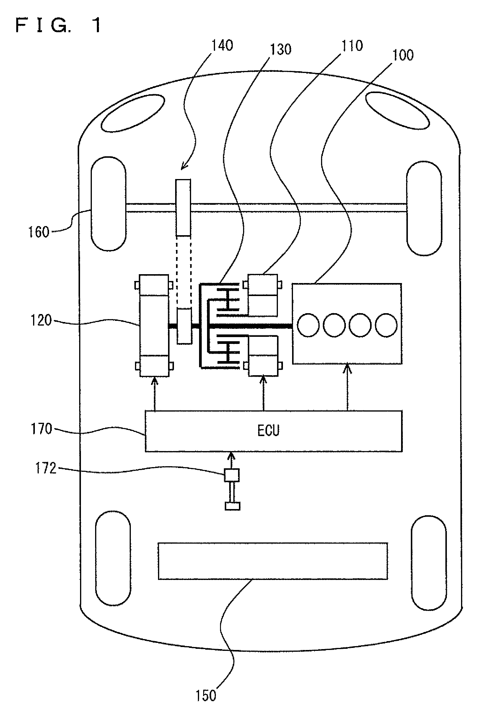
[0021]Referring to FIG. 1, a hybrid vehicle has an engine 100, a first motor generator 110, a second motor generator 120, a power split device 130, a reducer 140, and a battery 150. In the following description, a hybrid vehicle without a function of charging from an external power source will be described as an example. However, a plug-in hybrid vehicle having a function of charging from an external power source may be used.

[0022]Engine 100, first motor generator 110, second motor generator 120, and battery 150 are controlled by an ECU (Electronic Control Unit) 170. ECU 170 may divided into a plurality of ECUs.

[0023]This vehicle travels with a drive force supplied by at least one of engine ...


PUM


Abstract

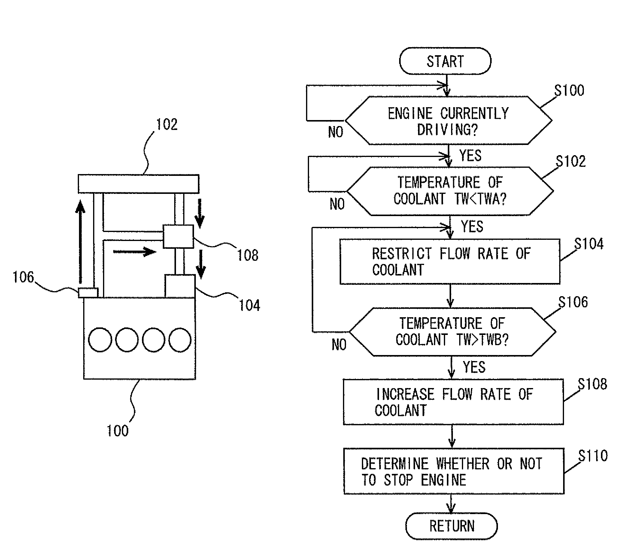
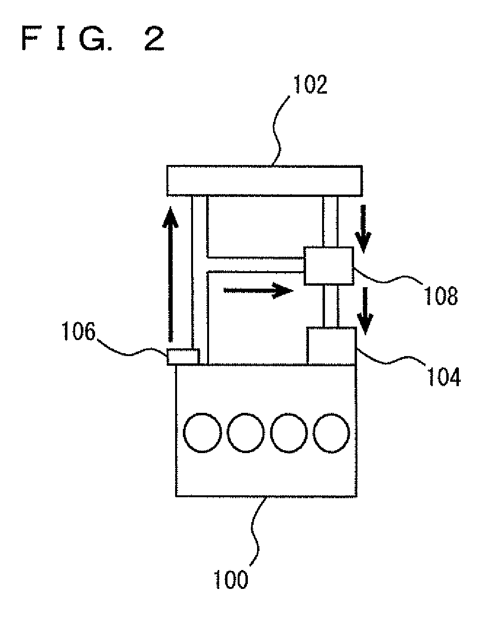
A control device is provided for an engine equipped with an electric oil pump for circulating coolant, and having a flow rate of the coolant restricted, when a temperature of the coolant is lower than a threshold value, as compared to a case where the temperature of the coolant is equal to or higher than the threshold value, and the engine control device includes a coolant temperature sensor detecting a temperature of the coolant, and a control unit stopping the engine in accordance with the temperature to be detected by the coolant temperature sensor after the pump is driven so as to increase the flow rate of the coolant, in a case where the flow rate of the coolant is restricted.

Description

TECHNICAL FIELD[0001]The present invention relates to a control device and control method for an engine, and more particularly to a technique of driving a pump for circulating engine coolant.BACKGROUND ART[0002]A vehicle having an engine is known. Many engines are cooled by using coolant. Coolant is circulated by a water pump. For example, an electric water pump is used. When the temperature of coolant is higher than a threshold value, coolant is circulated by an electric water pump to cool an engine. On the other hand, when the temperature of coolant is lower than a threshold value, the electric water pump is stopped to facilitate engine warm-up.[0003]The temperature of coolant is leveraged for controlling an electric water pump and also for performing various controls for an engine. However, in a state where the electric water pump is stopped, the difference between the temperature at a location where a coolant temperature sensor is provided and the temperature at a location remot...

Claims


Application Information

Patent Timeline
Patent Type & Authority Patents(United States)
IPC IPC(8): F01P7/16
CPCF01P7/164F02N11/0818F01P2050/24F01P2037/02B60W20/00Y02T10/48F02N2200/023B60W10/30B60W2710/182B60W10/06B60W2510/0676Y02T10/40
Inventor TERAYA, RYUTA
Owner TOYOTA JIDOSHA KK
Learn More